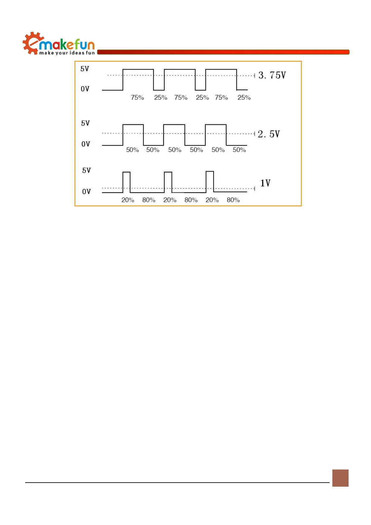
Figure 6-2 Diagram of pulse and voltage
For detailed use of the chip, please refer to《MotorDriverBoard\Datasheet\TB6612FNG.pdf》
Driving DC motor
The PS2X&Motor Driver Board has four DC motor interfaces, namely DC motor interface 1, DC motor
interface 2, DC motor interface 3 and DC motor interface 4, which can be directly connected to the drive via
the terminals. Connect 4 DC motors to DC motor interface 1, 2, 3, 4 (as shown in Figure 6-3). After
connecting the motor, connect the battery to the development board, turn on the power switch, and the
program starts running. We will see the motor will turn up, and the drive schematic of the DC motor is
shown in Figure 6-4.