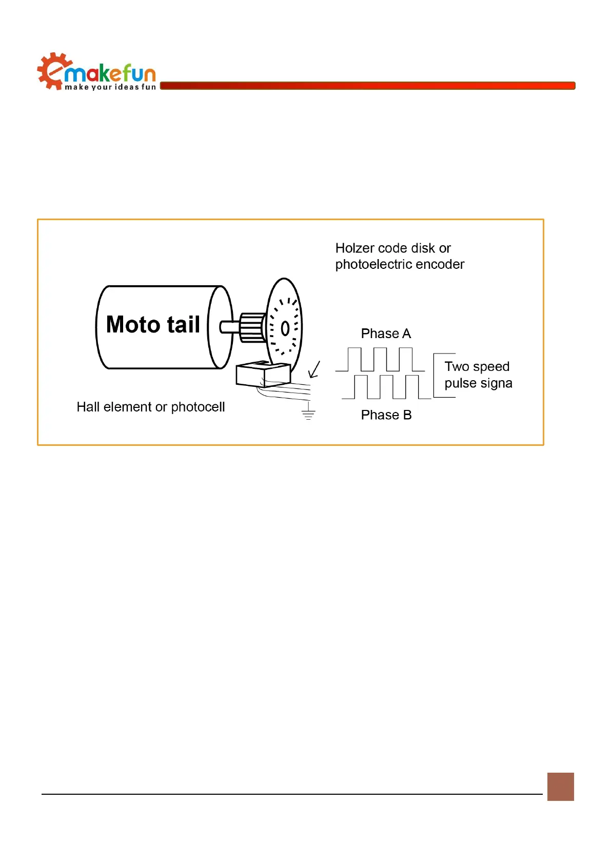
disc and a Hall element. The Hall code disc is equidistantly arranged with different magnetic poles on a
circular plate of a certain diameter. The Hall code disc is coaxial with the motor. When the motor rotates, the
Hall element detects and outputs several pulse signals. In order to judge the steering, two groups of square
wave signals having a certain phase difference are generally output. It can be seen that the encoders of both
principles aim to obtain the square wave signal of the AB phase output, and the method of use is the same.
The following is a simple schematic diagram.
Figure 8-1 Schematic diagram of the Coded Motor
Encoder wiring instructions
Specific to our encoder motor, we can look at the actual motor encoder. This is an incremental output Hall
encoder. The encoder AB phase output, so not only the speed can be measured, but also the steering can be
discerned. According to the wiring instructions in Figure 6-2-4, we only need to supply 5V power to the
encoder, and the square wave signal can be output through the AB phase when the motor rotates. The
encoder comes with a pull-up resistor, so no external pull-up is required and can be directly connected to the