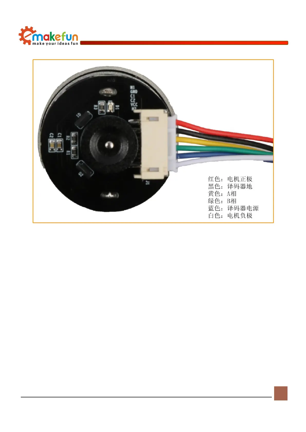
microcontroller IO for reading.
Figure 8-2 Encoder wiring diagram
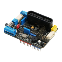
Drive Encode Motor
Connect a coding motor to port 1 and port 2 of the encoder motor as shown in Figure 8-3. The working
voltage of the encoder motor is between 5 and 12V. After connecting the motor to the line, find the encoded
motor test sample program in the sample program (sample program file path: load file ->
AdvancedExperiment -> Encoder -> Encoder.ino), burn the program to the development board, and then
turn on the driver. The power of the board will find that the two encoder motors will rotate synchronously.
The schematic diagram of the encoder motor is shown in Figure 6-4.