Emaldo Power Core User Manual
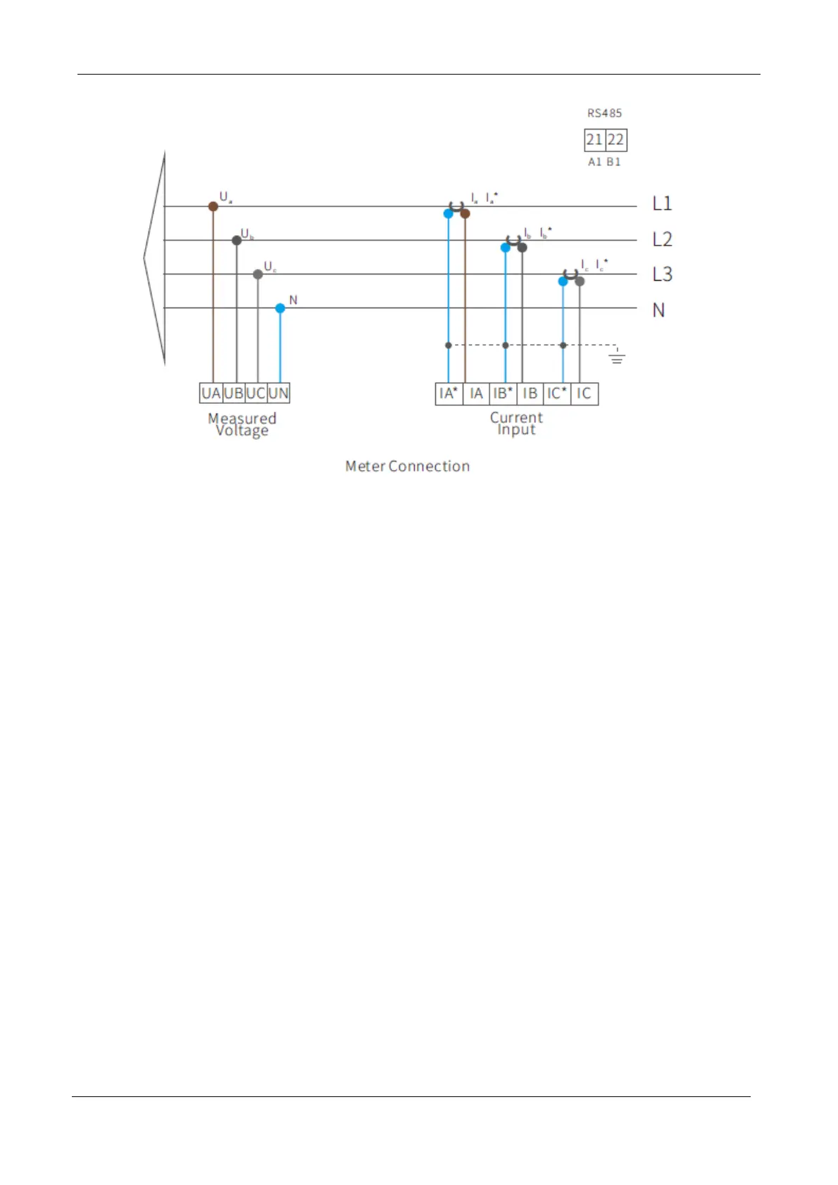
1. Insert the CT current sensor around the incoming line of the public power grid in the
household cabinet.
2. The red wire of the Phase A CT sensor is connected to the terminal Ia* at the bottom of the
instrument.
3. The black wire of the Phase A CT sensor is connected to the terminal Ia at the bottom of
the instrument.
4. The red wire of the Phase B CT sensor is connected to the terminal Ib* at the bottom of the
instrument.
5. The black wire of the Phase B CT sensor is connected to the terminal Ib at the bottom of
the instrument.
6. The red wire of the Phase C CT sensor is connected to the terminal Ic* at the bottom of the
instrument.
7. The black wire of the Phase C CT sensor is connected to the terminal Ic at the bottom of
the instrument.
8. Prepare one piece of grounding wire for earthing.
9. Prepare 4 pieces of voltage (Ua, Ub, Uc, UN) induction wires for connecting RCD in the
distribution box.