System component description
EMC VNX8000 Hardware Information Guide 39
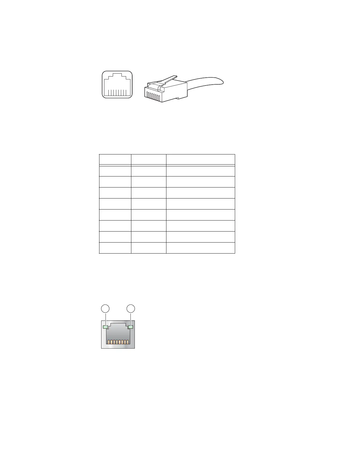
Control Station Ethernet (RJ-45) port and connector (adapter)
Figure 24 shows an example of the Ethernet RJ-45 port and cable connector.
Figure 24 Control Station Ethernet (RJ-45) port and connector (adapter)
Table 14 lists the Control Station Ethernet (RJ-45) pin signals used on the connector.
Control Station Ethernet (RJ-45) port LEDs
The Control Station (RJ-45) has two LEDs—a green LED to the left of the connector and a
bi-color (green/amber) LED to the right of the connector—that indicates the link/activity
and speed of the 1U Control Station (RJ-45) ports, respectively (Figure 25).
Figure 25 Control Station Ethernet (RJ-45) port LEDs
8 7 6 5 4 3 2 1
CNS-001749
Table 14 Control Station Ethernet (RJ-45) port and connector pinout
RJ-45 pin Signal Description
1 BI_DA+ Bidirectional pair A, +
2 BI_DA- Bidirectional pair A, -
3 BI_DB+ Bidirectional pair B, +
4 BI_DC+ Bidirectional pair C, +
5 BI_DC- Bidirectional pair C, -
6 BI_DB- Bidirectional pair B, -
7 BI_DD+ Bidirectional pair D, +
8 BI_DD- Bidirectional pair D, -
CNS-001748
21

 Loading...


