40 EMC VNX8000 Hardware Information Guide
System component description
Table 15 describes the link/activity and connection speed associated with the Control
Station (RJ-45) port LEDs.
Ethernet cable extensions for the Control Station B and MGMT ports
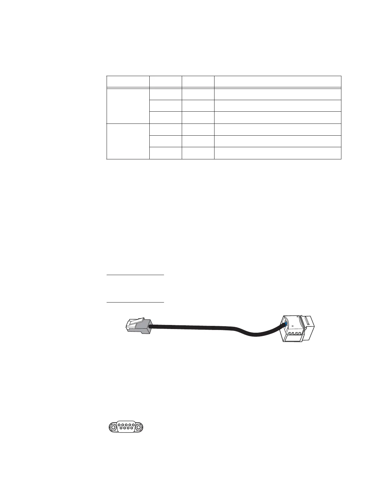
Each File/Unified VNX8000 platform 1U Control Station comes with two modular Ethernet
cable extensions (or patch cords) for the RJ-45 ports (labeled on the CS as B and MGMT,
respectively). These cables (Figure 26) allow you to extend the length of the Ethernet
cables from the CS 0, port B to Data Mover enclosure 0, management module B, port 1
and CS 0, MGMT port to the public LAN.
If your File/Unified VNX8000 platform includes a second optional 1U Control Station
(CS 1), another set of Ethernet cable extensions for the RJ-45 ports is provided. These
cables allow you to extend the length of the Ethernet cables from the CS 1, port B to Data
Mover enclosure 0, management module B, port 2 and CS 1, MGMT port to the public LAN.
Each cable includes a corresponding label clip to assist you during system cabling.
Note: If you received the File/Unified VNX8000 platform already installed in a cabinet rack
with all of the File/Unified VNX8000 platform components, all the cabling has already
been installed.
Figure 26 Example of an Ethernet extension (modular plug to modular jack) cable
Control Station serial console (DB-9) plug connector
The back of the File/Unified VNX8000 platform system 1U Control Station includes a
standard serial console Electronics Industries Association (EIA) RS-232 interface (DB-9)
plug connector. Notice the orientation of the pins (Figure 27).
Figure 27 Control Station serial console (DB-9) plug connector
Table 15 Control Station RJ-45 port LEDs
Led Color State Description
Left,
link/activity
(see location 1)
Green On Network/link connection
Green Blinking Transmit/receive activity
— Off No network/link connection
Right, link
speed
(see location 2)
Green On 100-Mb/s connection
Amber On 1000-Mb/s (or 1-Gb/s) connection
— Off 10-Mb/s connection (if left LED is on or blinking)
VNX-000564
Pin 1
5
6 9
VNX-000526

 Loading...


