System component description
EMC VNX8000 Hardware Information Guide 41
Note: The pin designations shown in Figure 27 on page 40 are for reference only.
Table 16 lists the 1U Control Station Ethernet (DB-9) pin signals used on the connector.
Control Station modem (DB-9) plug connector
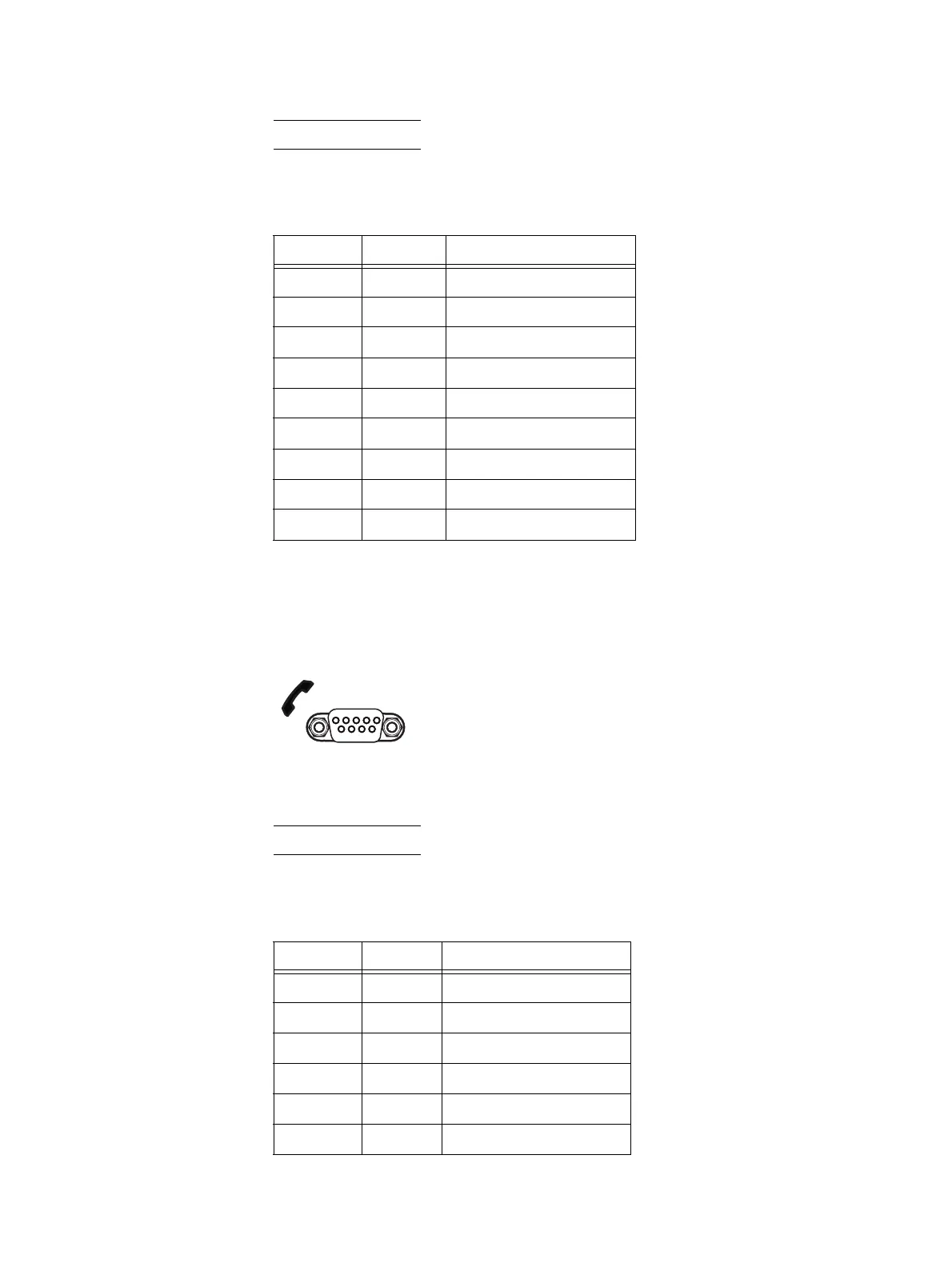
The back of the File/Unified VNX8000 platform 1U Control Station includes a standard
modem serial interface (DB-9) plug connector (labeled with a telephone handset icon and
the numbers 1 0 1 0 on the left). Notice the orientation of the pins (Figure 28).
Figure 28 Control Station modem (DB-9) plug connector
Note: The pin designations shown in Figure 28 are for reference only.
Table 17 lists the 1U Control Station Ethernet (DB-9) pin signals used on the connector.
Table 16 Control Station (DB-9) plug connector pinout
DB-9 Pin Signal Description
1 CD Carrier detect
2RXDReceived data
3 TXD Transmitted data
4 DTR Data terminal ready
5GNDGround
6DSRData set ready
7 RTS Request to send
8 CTS Clear to send
9 RI Ring indicator (not used)
Pin 1
5
6 9
1 0 1 0
VNX-000527
Table 17 Control Station modem (DB-9) plug connector pinout
DB-9 Pin Signal Description
1 CD Carrier detect
2 RXD Received data
3 TXD Transmitted data
4 DTR Data terminal ready
5GNDGround
6DSRData set ready

 Loading...


