Disk-array enclosures
EMC VNX5400 Hardware Information Guide 85
Each LCC independently monitors the environmental status of the entire enclosure, using
a microcomputer-controlled monitor program. The monitor communicates the status to
the storage processor, which polls disk enclosure status. LCC firmware also controls the
SAS PHYs and the disk-module status LEDs.
As shown in Figure 62 on page 84, an enclosure ID
13
indicator is located on each LCC.
Each LCC also includes a bus (back-end port) identification indicator. The SP initializes
the bus ID when the operating system is loaded.
Note: An LCC might be in either the A slot, as shown, or the B slot above it, depending on
the DAE placement within a system. For example, the front DAE in some systems is in slot
A; the rear enclosure LCC is inverted, and in slot B.
LCC input/output ports and connectors
The 3U, 15 (3.5-inch) DAE LCC supports the following I/O ports on the rear:
◆ Two 6-Gb/s by four-lane mini-SAS ports
◆ One management (RJ-12) connector to the SPS (not used in the VNX5400 platform)
6-Gb/s mini-SAS x4 ports — The 3U DAE LCC supports two (one input and one output)
6-Gb/s mini-SAS x4 ports (labeled 6Gb SAS x4) on the rear of each LCC (A and B). This port
provides an interface for SAS and NL-SAS drives on the DAE. This port is a 26-circuit SAS
small form-factor 8088 (SFF-8088) specification (socket or receptacle) using an SFF-8088
specification mini-SAS 26-circuit cable (plug) with a pull tab.
Note: Each SAS cable is keyed with an
in
and
out
connection to prevent incorrect cabling.
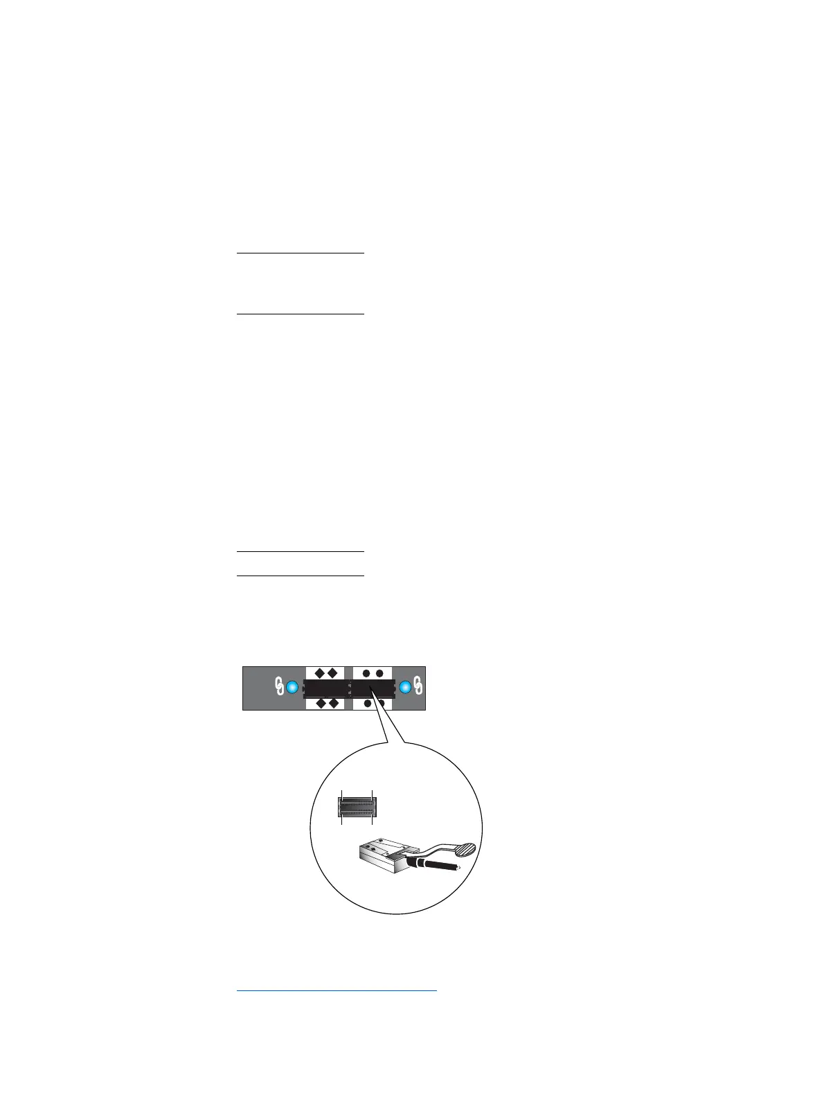
Figure 63 shows an example of the mini-SAS port connector (socket) and cable connector
(plug) with pull tab.
Figure 63 6-Gb/s mini-SAS port and cable connector
13. The enclosure ID is sometimes referred to as the enclosure address (EA).
3U, DAE LCC B 6-Gb/s mini-SAS ports
X4
6Gb SAS
Pin A1 A13
B1 B13

 Loading...


