Menu 5 Introduction
Parameter
x.00
Parameter
description format
Keypad and
display
Serial
communications
CT Modbus
RTU
PLC Ladder
programming
CTSoft Menu 0
Advanced parameter
descriptions
76 Commander SK Advanced User Guide
www.controltechniques.com Issue Number: 9
The rated voltage is used in conjunction with the motor rated frequency (Pr 5.06) to define the voltage to frequency characteristic applied to the motor.
The following operating methods selected by Pr 5.14 are used to define the drive frequency to voltage characteristic.
Open-loop vector mode: Ur S, Ur A, Ur or Ur I
A linear characteristic is used from 0Hz to rated frequency, and then a constant voltage above rated frequency. When the drive operates between
rated frequency/50 and rated frequency/4, full vector based stator resistance (Rs) compensation is applied. However there is a delay of 0.5s when the
drive is enabled during which only partial vector based compensation is applied to allow the machine flux to build up. When the drive operates
between rated frequency/4 and rated frequency/2 the Rs compensation is gradually reduced to zero as the frequency increases. For the vector
modes to operate correctly the stator resistance (Pr 5.17), motor rated power factor (Pr 5.10) and voltage offset (Pr 5.23) are all required to be set-up
accurately.
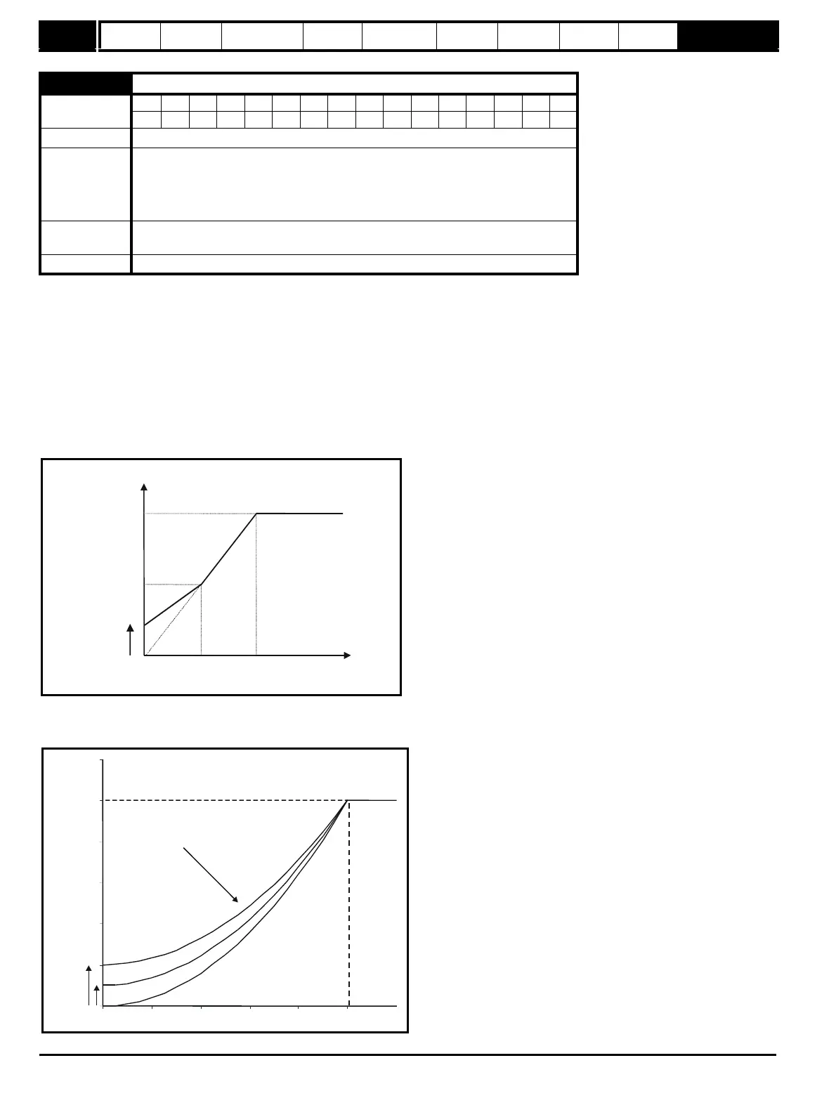
Fixed boost mode: Fd
A linear characteristic is used from 0Hz to rated frequency, and then constant voltage above rated frequency. Low frequency voltage boost as defined
by Pr 5.15 is applied as shown below.
Square law mode: SrE
A square law characteristic is used from 0Hz to rated frequency, and then constant voltage above rated frequency. Low frequency voltage boost
raises the start point of the square law characteristic as shown below.
5.09 Motor rated voltage {08}
Coding
Bit SP FI DE Txt VM DP ND RA NC NV PT US RW BU PS
1 1 111
Range 0 to AC_VOLTAGE_SET_MAX V
Default
110V rating drive: 230V
200V rating drive: 230V
400V rating drive: Eur: 400V, USA: 460V
575V rating drive: 575V
690V rating drive: 690V
Second motor
parameter
Pr 21.09
Update rate 128ms
Voltage
boost Pr
5.15
Output
voltage
Pr
5.09
Pr / 2
5.09
Pr / 2
5.06
Pr
5.06
Output
frequency
Output voltage characteristic
Pr
5.09
Pr
5.15
Pr
5.06
Pr + [(freq/Pr ) x (Pr - Pr )]
5.15 5.06 5.09 5.15
2