3.3.2 Install the T-Slot transducer holder
Procedure
1. Ensure that the Daniel 3410 Series Ultrasonic Gas Flow Meter transducer port,
mount, and T-Slot transducer holder assembly are clean and free of debris.
2. Insert the transducer (parts are keyed and can only be assembled one way) into the
stalk or into the new transducer holder if no stalk is required. Do not use any
lubricant on the O-rings or contacts of the transducers.
NOTICE
Ensure that the transducers identified as belonging to end 1 are installed on end 1
of the meter housing and those identified as belonging to end 2 are installed on end
2 of the meter housing.
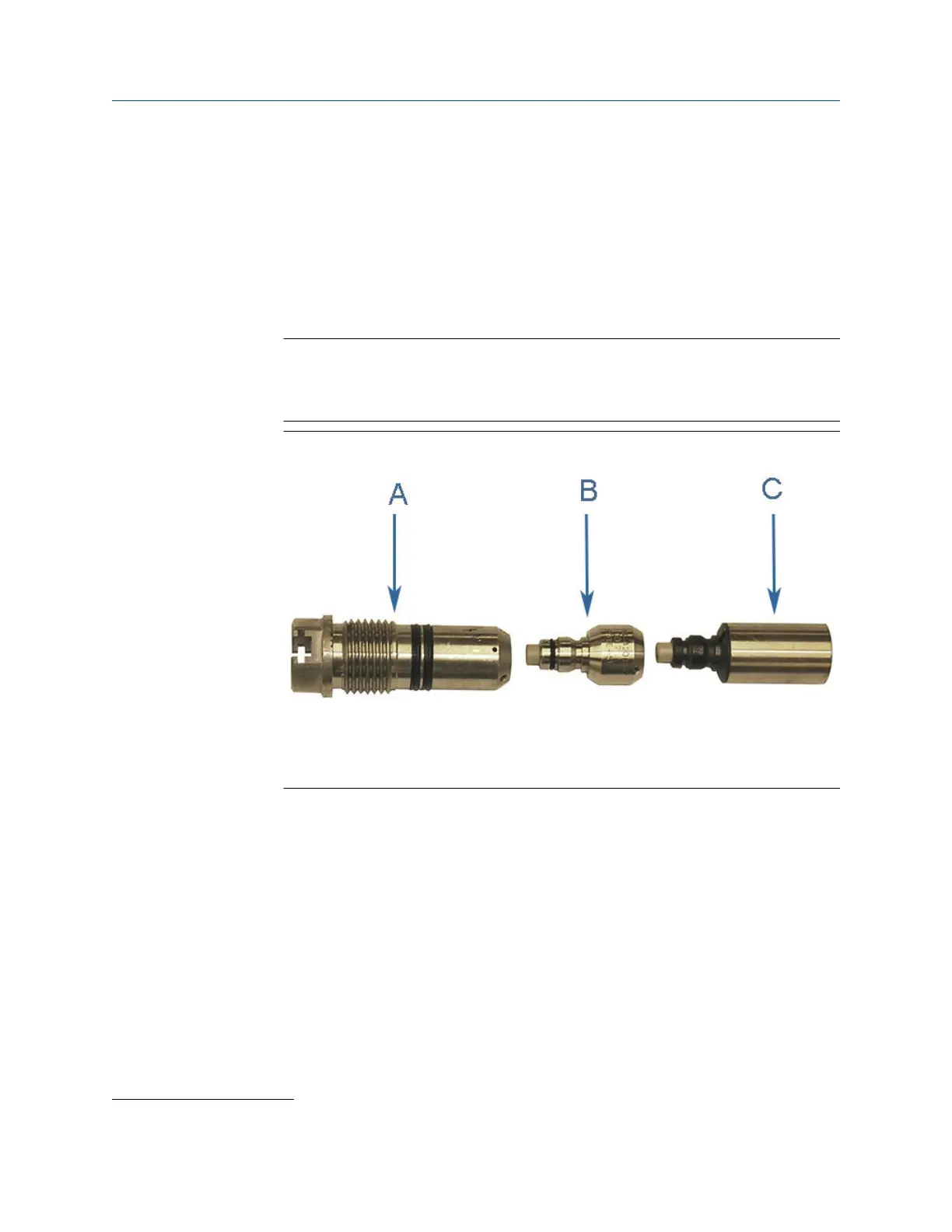
Figure 3-6: Transducer holder, stalk and transducer assembly
A. Transducer holder
B. Stalk
C. Transducer assembly
3. Replace the O-rings and backup rings on the transducer holder. Make sure the
contoured side of the backup ring faces away from the transducer holder. It is highly
recommended that the O-rings be replaced when the transducer is removed from
the holder/stalk.
4. Use a 1/16” hex driver to equally tighten the three Allen set screws on the
transducer holder to secure the transducer assembly and the stalks (if installed).
5. Apply a light coat of Molykote 111
(1)
. Silicone grease or equivalent to the
transducer holder O-rings.
6. Ensure that the transducer port, mount, and T-Slot transducer assembly are clean
and free of debris.
7. Apply a small amount of nickel anti-seize compound (P/N 2-9-9960-134) to the
outer threads of the transducer holder.
(1)
Molykote 111 is a trademark of Dow Corning Corporation, U.S.A.
Maintenance and Troubleshooting manual Meter repairs
P/N 3-9000-791 August 2021
Maintenance and Troubleshooting manual 55

 Loading...


