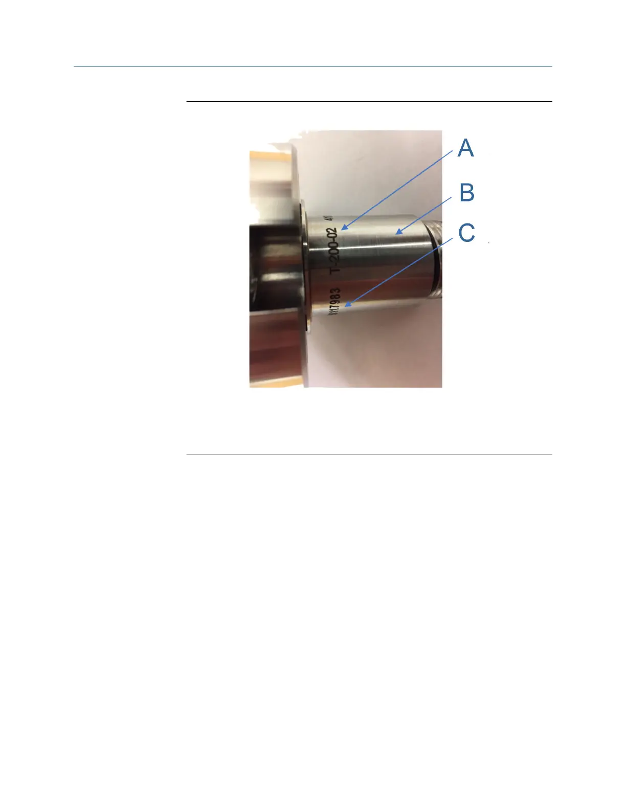
Figure 3-11: T-200 transducer stalk assembly configuration
A. Stalk assembly configuration
B. Transducer stalk
C. Stalk assembly serial number
3. Ensure that the setting of the transducer capsule assembly matches the stalk
assembly configuration (see Table 3-2). The setting of a transducer capsule
assembly is indicated by the number next to the slot where the tap is located (see
Figure 3-10), i.e. 1, 2, ... 8. The stalk assembly configuration is labeled on the
transducer stalk, next to its serial number (see Figure 3-11), i.e. -01, -02, ... -13 after
"T-200". If adjustment is needed:
a) Use one hand to hold the crystal holder and the other hand to hold the
transformer housing (see Figure 1).
b) Turn the transformer housing clock wise by 90 degrees and slide it slowly to
align the tab to the proper position according to Table 3-2.
c) Turn the transformer housing counter-clock wise by 90° to let the tap snap
into the correct slot. Ensure the tap is secured in the slot.
4. Hold the transducer capsule assembly vertically and apply a small amount of
Acoustic Coupling Fluid (P/N: 1-360-01-650) to the surface of Kapton tape.
5. Carefully spread the coupling fluid on the surface of Kapton tape using the tip of the
plastic bottle for the coupling fluid.
Maintenance and Troubleshooting manual Meter repairs
P/N 3-9000-791 August 2021
Maintenance and Troubleshooting manual 63

 Loading...


