Note
Do not press the Kapton tape while spreading the coupling fluid.
6. Wait for 30 - 60 seconds to let the coupling fluid spread more evenly on the surface.
7. Insert the transducer capsule assembly into the transducer stalk while aligning the
anti-rotation pin on the capsule with the slot on the inner surface of the stalk.
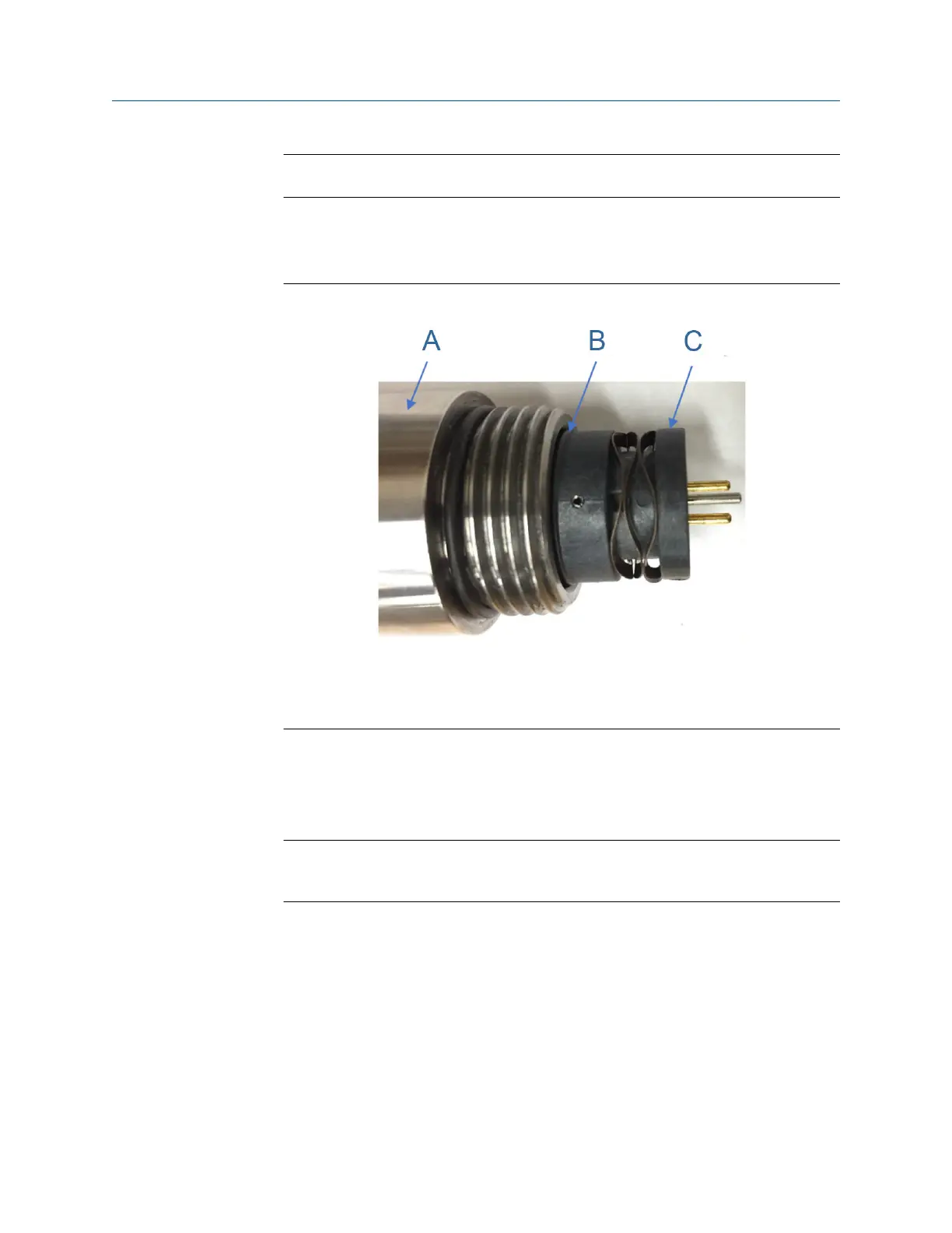
Figure 3-12: Length verification of T-200 transducer capsule assembly
A. Transducer stalk
B. Indicator ring
C. Capsule assembly
8. Make sure that the indicator ring on the transducer capsule assembly is flush with
the end of the transducer stalk (see Figure 3-12) to ensure the capsule is set to the
correct length.
9. Screw the transducer retainer on the stalk and use a 1 ⅛" wrench to bottom out.
Note
Do not torque down the transducer retainer to avoid damages to the anti-rotation
pins.
10. Connect the transducer chordset to the transducer retainer. The internal connector
of the transducer chordset is keyed and will only go on one way.
11. Secure the transducer cabling nut by turning clock wise. Ensure the cable nut
threads are correctly aligned.
12. Repeat Step 1 through Step 11 for other transducer assemblies if their transducer
capsule assemblies were replaced.
13. Continue with Section 3.5.3 to use the Daniel MeterLink Transducer Swap-out
Wizard to update delta delay time.
Meter repairs Maintenance and Troubleshooting manual
August 2021 P/N 3-9000-791
64 Models 3415, 3416 and 3417 GUSM

 Loading...


