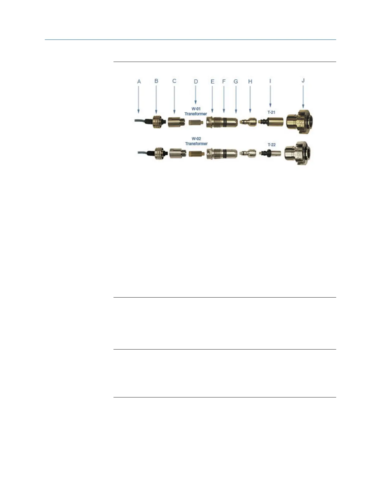
Figure 3-5: T-21 and T-22 transducer assembly
A. Transducer cable (max. length 15 ft.)
B. Transducer cable nut and chordset
C. Transformer retainer (Standard P/N 1-360-01-958 or High Temperature P/N
1-360-01-978)
D. Transformer assembly T-21 (W-01 P/N 1-360-03-090) or T-22 (W-02 P/N
1-360-03-110)
E. Transducer holder
F. Transducer holder O-rings
G. Set screw holes (end of transducer holder)
H. Transducer stalk (optional)
I. Transducer assembly
J. Mount and backup O-ring
6. Loosen the T-Slot transducer holder assembly with a 1 1/4” socket. Carefully
remove the T-Slot transducer assembly.
7. Loosen the three Allen setscrews with a 1/16” hex driver securing the transducer
assembly and stalk, if installed. Carefully remove the old transducer by pulling it
from the T-Slot transducer holder assembly without rotating.
Important
Record the “L” dimension of the removed transducers which is used to update the
meter configuration after all of the transducers are replaced. Make sure you have
the report sheet containing the “L” dimension, Delay Time, and Delta Delay Time
for the replacement pair of transducers to use during the Transducer Swap-out
procedure in Daniel MeterLink.
8. Clean the transducer holder with a dry cloth.
Meter repairs Maintenance and Troubleshooting manual
June 2019 P/N 3-9000-769
60 Gas Ultrasonic Flow Meters

 Loading...


