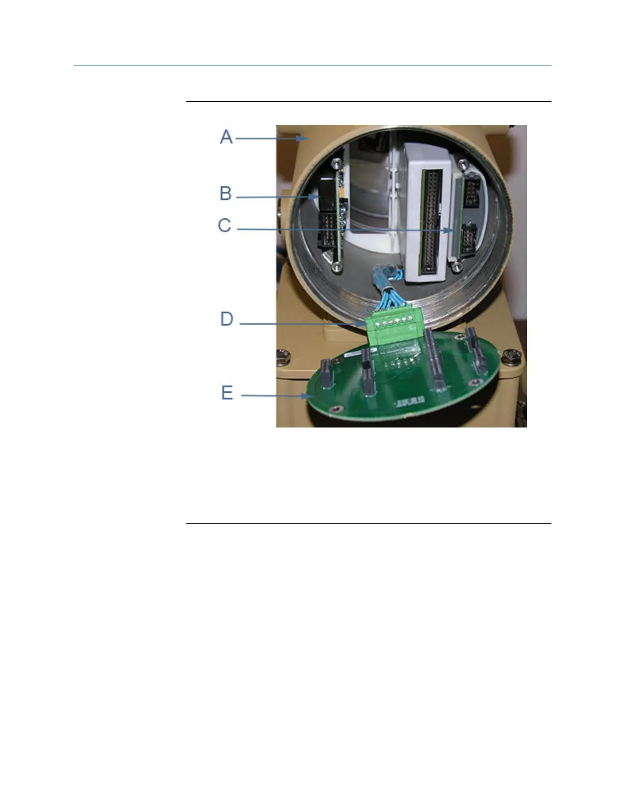
Figure 3-28: Backplane board replacement
A. Non-terminal end of Transmitter Electronics Enclosure
B. Power Supply board
C. I.S. Barrier board (inside the Guide Plate)
D. Acquisition cable
E. Backplane board
6. Use a 3 mm flat head screw driver and disconnect the Acquisition Cable terminal
block from the Backplane. Unplug the Acquisition Cable from the Backplane.
7. Remove the Power Supply (if it was not removed with the Backplane board) and I.S.
Barrier boards from the enclosure. The I.S. Barrier Board has a notched tab that
secures the board to the Guide Plate.
8. Attach the Acquisition Cable terminal block to the new Backplane Board and plug
the Power Supply Board and I.S. Barrier board into the Backplane board.
9. Insert the Backplane (with the Power Supply and I.S. Barrier Boards attached to the
Backplane) into the enclosure.
10. Fully seat the CPU Module and Optional I/O Module onto the Backplane board.
11. Install the four Phillips head screws to secure the Backplane to the enclosure
standoffs.
12. Reinstall the terminal blocks on the CPU Module, Optional I/O Module (if installed),
and the Power Supply board using a 3 mm flat head screw driver.
Meter repairs Maintenance and Troubleshooting manual
June 2019 P/N 3-9000-769
92 Gas Ultrasonic Flow Meters

 Loading...


