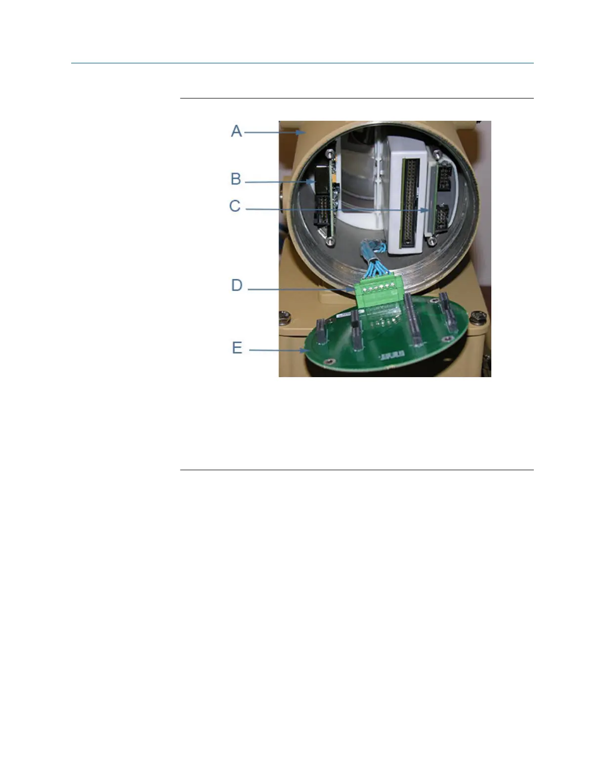
Figure 3-29: I.S. Barrier board replacement
A. Non-terminal end of Transmitter Electronics Enclosure
B. Power Supply board
C. I.S. Barrier board (inside the Guide Plate)
D. Acquisition cable
E. Backplane board
6. Remove the I.S. Barrier Board from the Guide Plate on the right side of the
enclosure.
7. Install the new I.S. Barrier board onto the Backplane Board and seat the Power
Supply board onto the Backplane board.
8. Insert the Backplane, I.S. Barrier board and the Power Supply Board into the
enclosure.
9. Fully seat the CPU Module and Optional I/O Module onto the Backplane Board.
10. Attach the Backplane to the enclosure standoffs with the four Phillips head screws.
If the Local Display Module is installed on the Backplane, use a flat blade screw
driver and install the four flat-head screws into the enclosure standoffs.
11. Reinstall the J7 terminal block, if removed, on the Backplane board. Re-install the
CPU Module, Optional I/O Module (if installed) and the Power Supply.
12. Recheck the connections, wiring and switch settings before replacing the end caps.
13. If replacing other electronics, continue with the following procedures before
replacing the end caps and sealing the enclosure.
Meter repairs Maintenance and Troubleshooting manual
June 2019 P/N 3-9000-769
94 Gas Ultrasonic Flow Meters

 Loading...


