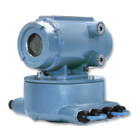
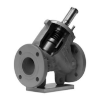
Table 1-2: Part description for the LME with Internal Totalizer
Item
number
Description Part number Quantity
required
1
(1)
Cover (SS/ALUM) 899-10-230-60/70 1
2 Electronics enclosure (SS/ALUM) 899-10-110-60/70 1
3 Plug pipe hex socket 154717-019 2
4 Grounding cap B18934-004 2
5 Mounting bracket 899-10-230-50 1
6
(2)
Socket head screw 899-10-230-52 4
7 Warning tag-Hazard 899-00-328-04 1
8 Socket head screw 899-10-230-61 4
10 2818 Dual channel preamplifier 1-504-05-550 1
11 Socket head screw 899-10-230-65 2
12
(3)
Wiring diagram for 2818 Dual channel
preamplifier
899-10-230-69 1
13 O-ring NBR 2-4-9163-245 1
14 O-ring FKM 1500093-022 1
15 Washer plastic 1-562-01-827 1
16 Clamp cover 1-504-90-165 1
17 Socket head screw 1-555-27-001 1
19 Display and terminal block 899-10-230-30/32 1
20 Female standoff 899-10-230-63 4
21 Machine screw 899-10-230-64 4
(1) Enclosure housing and cap material: aluminum. Optional: stainless steel.
(2) Screw length varies on LTM sizes. The screwa are not included within the part number package.
(3) 2818 Dual channel shown. For other preamplifier options, refer to Interface parameters.
NOTICE
The joint between the LME cover and housing is a threaded joint. The joint between the
LME housing and sensor housing is a cylindrical joint which has an axial length of 25.4 mm
(1 in) and a clearance of 0.038 mm (0.0015 in).
User manual Introduction
P/N 3-9008-515 March 2019
User manual 19

 Loading...


