96 Appendix 1 Parameters
EV2000 Series Universal Variable Speed Drive User Manual
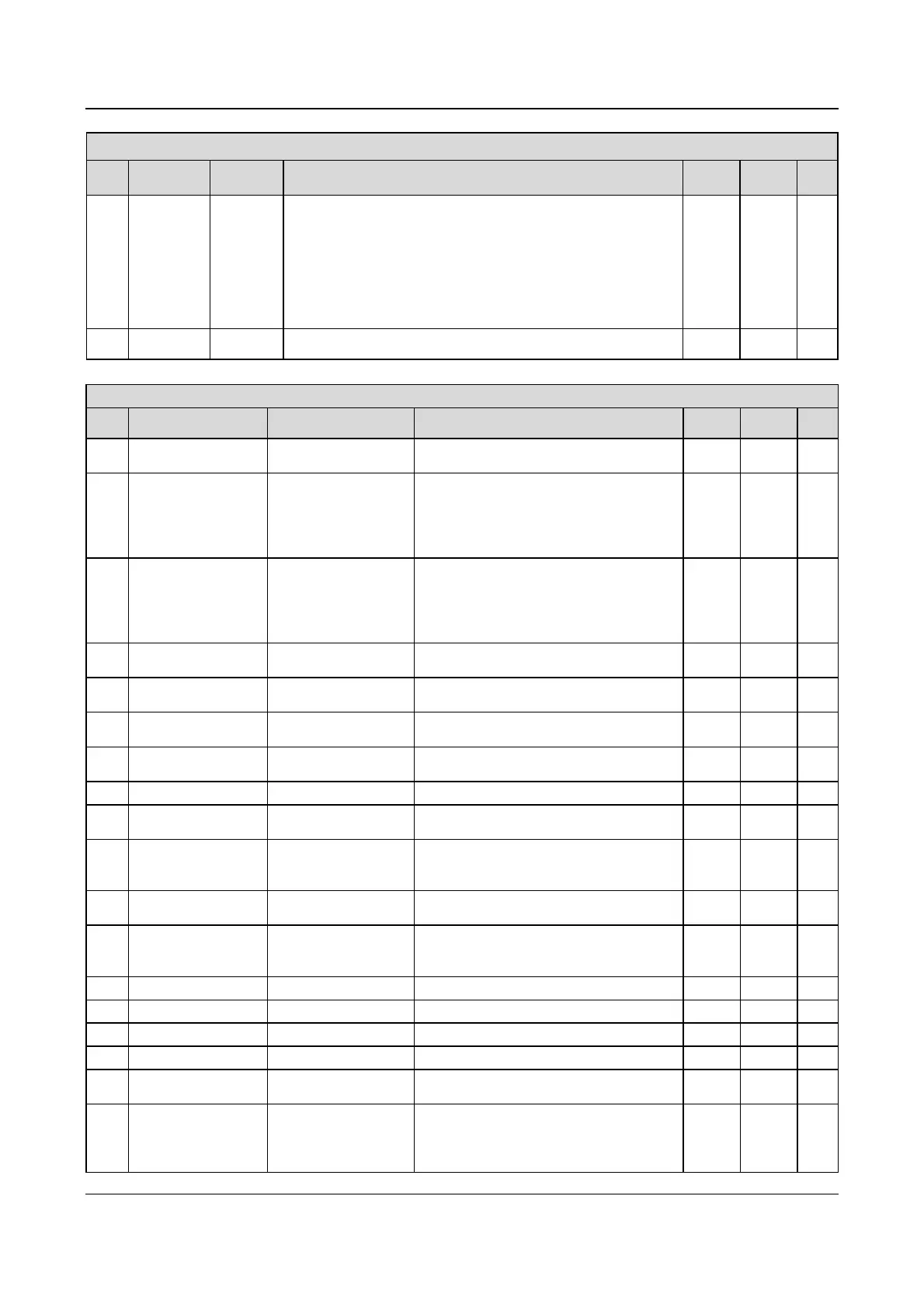
Group F4: Operating Parameters
Para Name LCD Display Setting range Unit
Factory
setting
Modif.
F4.13 Phase 7 setup
STAGE 7
SET
Unit’s place of LED: Frequency setting
0:Pre-set frequency 7(F3.29) 1:Decided by F0.00 parameter
2:Close loop reference 7(F5.26) 3:Decided by F5.01 parameter
Ten’s place of LED: Running direction selection
0:Run forward 1:Run reverse
2:Decided by operating instructions
Hundred’s place of LED: Acc/Dec time selection
0:Acc/Dec time 1 1:Acc/Dec time 2
2:Acc/Dec time 3 3:Acc/Dec time 4
1 000
○
F4.14
Operating time
in Phase 7
STAGE 7
TIME
0.0 ~ 6500 0.1 20.0
○
Group F5: Close-loop control parameters
Para. Name LCD Display Setting range Unit
Factory
setting
Modif.
F5.00
Close-loop function
selection
CLOSELOOP FUNC
SELE
0:disabled
1:enabled
1 0
×
F5.01
Reference channel
selection
REF CHAN SELE
0:Digital input; (F5.02=6, F5.06, others, F5.05)
1:VCI; 2: CCI;
Note: For speed-loop, analog reference of 10V
corresponds to the maximum frequency defined by
F0.05
1 1
○
F5.02
Feedback channel
selection
FEEDBACK CHAN SELE
0:VCI (0~10V) 1:CCI (analog input)
2:VCI+CCI 3:VCI-CCI
4:Min{VCI,CCI} 5:Max{VCI,CCI}
6:Pulse; (PG close loop signal/dual loop is decided
by terminal)
1 1
○
F5.03
Filter of reference
channel
REF FILTER CONST 0.01~50.00s 0.01s 0.50s
○
F5.04
Filter of feedback
channel
FEEDBACK FILTER
CONST
0.01~50.00s 0.01s 0.50s
○
F5.05
Set reference in digital
mode
DIGITAL REF 0.00V~10.00V 0.01 0.00
○
F5.06
Speed reference set in
close loop
CLOSELOOP REF 0~39000rpm 1 0
○
F5.07 PG setting PULSE NUMBER SELE 1~9999 1 1024
○
F5.08 Min reference MIN REF
0.0%~(F5.10) (Ratio of Min reference to base
value of 10V/20mA)
0.1% 0.0
○
F5.09
Feedback value
corresponding to the Min
reference
MIN FEEDBACK
0.0~100.0%
(Ratio of Min reference to base value of
10V/20mA)
0.1% 20.0%
○
F5.10 Max reference MAX REF
(F5.08)~100.0% (Ratio of Max reference to
base value of 10V/20mA)
0.1% 100.0%
○
F5.11
Feedback value
corresponding to the
Max reference
MAX FEEDBACK
0.0~100%
(Ratio of Max reference to base value of
10V/20mA)
0.1% 100.0%
○
F5.12 Proportional gain KP PROPORTION GAIN 0.000~9.999 0.001 0.050
○
F5.13 Integral gain Ki INTEGRATION GAIN 0.000~9.999 0.001 0.050
○
F5.14 Sampling cycle SAMPLE CYCLE 0.01~50.00s 0.01s 0.50s
○
F5.15 Limits of deviation ERROR LIMIT 0.0~20.0%(corresponding to close loop reference) 0.1% 2.0%
○
F5.16
Close loop adjustment
characteristic
CLOSELOOP FEATURE
0:Forward 1:Reverse
Note: reference has no connection with speed
1 0
×
F5.17
Integral adjustment
selection
INTEGRATION SELE
0:Stop the Integral adjustment when the frequency
reaches the upper limit or lower limit.
1:Continue the Integral adjustment when the
frequency reaches the upper limit or lower limit.
1 0
×
 Loading...


