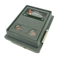
4195KA, KB, KC, and KS Controllers
Instruction Manual
Form 5207
April 2007
2-3
HEX HEAD
CAP SCREW
(KEY 66)
LOCK
WASHER
(KEY 67)
ROUND
HEAD
MACHINE
SCREW
(KEY 70)
BRACKET
(KEY 68)
TOP VIEW
36A9760-A
A6733 / IL
84
(3.29)
63
(2.49)
306
(12.06)
14 R
(0.56)
236
(9.31)
mm
(INCH)
13
(0.50)
62
(2.43)
REAR VIEW DIMENSIONS OF
PANEL CUTOUT
Figure 2-3. Panel Mounting
Process Pressure Connection
The connection marked A on the bottom of the case
is the process input for all Bourdon tube controllers
and those capsular element controllers used in
vacuum pressure applications. The connection
marked B is the process input for capsular element
controllers used in positive pressure and compound
pressure applications. See figure 2-5 for the location
of the A and B connections.
When installing process piping, follow accepted
practices to ensure accurate transmission of the
process pressure to the controller. Install a
three-valve bypass, shutoff valves, vents, drains, or
seal systems as needed in the process pressure
lines. If necessary, install a needle valve in a
process pressure sensing line to dampen pulsations.
If the instrument is located such that the adjacent
process pressure lines are approximately horizontal,
HEX HEAD
CAP SCREW
(KEY 66)
LOCKWASHER
(KEY 67)
BRACKET
(KEY 68)
TOP VIEW
36A9761-B
A6734 / IL
161
(6.35)
260
(10.25)
152
(6.00)
62
(2.43)
13
(0.50)
REAR VIEW
mm
(INCH)
13
(0.50)
Figure 2-4. Wall Mounting
the lines should slope downward to the instrument
for liquid-filled lines and upward toward the
instrument for gas-filled lines. This reduces the
possibility of air becoming trapped in the sensor with
liquid-filled lines or of condensation becoming
trapped in gas-filled lines. The recommended slope
is 83 millimeters per m (1 inch per foot).
If the controller is being used in conjunction with a
control valve to control pipeline pressure, connect
the process pressure line in a straight section of pipe
approximately 10 pipe diameters away from the
valve and also away from bends, elbows, and areas
of abnormal fluid velocities. For pressure-reducing
service, the process pressure line must be
connected downstream of the control valve. For
pressure-relief service, the process pressure line
must be connected upstream of the control valve.

 Loading...


