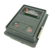
4195KA, KB, KC, and KS Controllers
Instruction Manual
Form 5207
April 2007
6-5
DEFLECT LOWER PORTION OF THE SLOT
AND LIFT THE SCALE UP AND OFF
W3440 / IL
W3492 / IL
Figure 6-1. Changing the Scale
Replacing the Process Pressure Scale
WARNING
Refer to the Maintenance WARNING
on page 6-1.
CAUTION
To prevent the pointer or set point
indicator from rubbing on the cover or
scale and producing an inaccurate
indication, take care not to bend the
process pointer or the set point
indicator while performing the
following procedure.
Refer to figure 6-1.
CLEAN-OUT
WIRE
RELAY
TAB
EXHAUST PORT
(NO O-RING
USED)
O-RINGS
(KEY 15)
RELAY
MOUNTING
SCREWS
(KEY 10)
W5744 / IL
O-RING
(KEY 13)
Figure 6-2. Relay Construction
1. Adjust the set point indicator (either manually or
with the remote set point pressure) to the mid-scale
mark on the process scale.
2. Remove the four self-tapping screws (key 37).
3. Slide the process scale (key 61) downward so
that the top of the slot touches the set point
indicator. Deflect the lower portion of the slot
outward and carefully slide the scale up and off,
clearing the set point indicator as shown in
figure 6-1.
4. To install the replacement scale, deflect the lower
part of the slot slightly so that the scale slides
downward over the set point indicator and under the
process pointer.
5. Secure the scale with the four self-tapping
screws (key 37).
6. If the controller has remote set point (suffix letter
M), perform the appropriate remote set point zero
and span calibration procedure in Section 3, 4, or 5.
7. Perform the appropriate process indicator zero
and span calibration and the flapper alignment
procedures in Section 3, 4, or 5.

 Loading...


