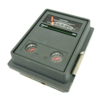
4195KA, KB, KC, and KS Controllers
Instruction Manual
Form 5207
April 2007
4-7
2. Set the proportional band between DIRECT and
REVERSE.
3. Apply remote set point pressure equal to the
lower range limit.
4. The set point indicator should indicate the
process scale lower limit. If not, loosen the remote
set point zero adjustment locking screw and adjust
the remote set point zero adjustment screw until the
set point indicator aligns with the process scale
lower limit. Tighten the zero adjustment locking
screw.
5. Apply remote set point pressure equal to the
upper range limit.
6. The set point indicator should indicate the
process scale upper limit. If not, adjust the remote
set point span adjustment screw to correct one-half
the error as follows: clockwise to increase span for a
low indication; counterclockwise to decease span for
a high indication.
7. Repeat steps 3 through 6 until the error is
eliminated.
8. Adjust the remote set point pressure to the
mid-range value.
9. Make sure the set point indicator is within ±1
percent of the mid-scale mark, and if so, proceed to
step 12. If the set point indicator is not within 1
percent, but is within ±2 percent of the mid-scale
mark, proceed with step 10. If the set point indicator
is not within ±2 percent, proceed to the remote set
point zero and span adjustment procedure in the
Maintenance section.
10. Loosen the remote set point zero adjustment
locking screw and adjust the remote set point zero
adjustment screw to correct for half the error at mid
scale. Tighten the zero adjustment locking screw.
11. Apply remote set point pressure equal to the
lower and upper range limits and make sure the set
point indicator is within ±1 percent.
12. If necessary, perform the process indicator zero
and span calibration procedure in this section.
Otherwise, perform the flapper alignment procedure
in this section.
Flapper Alignment
Note
Perform the process indicator zero
and span calibration procedure and,
for controllers with remote set point
(suffix letter M), the remote set point
zero and span calibration procedure
before the flapper alignment.
Flapper leveling screw numbers and adjustments
are shown in figure 4-3. Key number locations are
shown in figure 7-1.
Provide a means of measuring the controller output
pressure by connecting the controller output to a
pressure gauge (open-loop conditions must exist).
Do not apply supply pressure at this time.
Note
4195KB and KC Series controllers with
anti-reset windup (suffix letter F) are
supplied with two O-rings (key 52),
valve cover (key 51), and two machine
screws (key 53). Use these parts in the
next step.
1. For controllers with anti-reset windup (suffix letter
F), record the direction of the arrow on the anti-reset
windup relief valve (key 55). Remove the relief valve
and install the two O-rings (key 52) and valve cover
(key 51) supplied with the controller. Secure the
valve cover with the two machine screws (key 53)
provided.
2. If necessary, remove the two machine screws
(key 6) and lift off the proportional band indicator
cover (key 36).
3. If the controller has the external feedback option
(available with the 4195KB Series only), connect the
controller output to the external feedback
connection. See figure 2-5 for the location of the
output and external feedback connections.
4. Provide regulated supply pressure to the
controller. Do not exceed the normal operating
pressure in table 1-6.
5. For a controller with manual set point, move the
set point indicator to the mid-scale mark on the
process scale. For a controller with remote set point
(suffix letter M), adjust the remote set point pressure
until the set point indicator is at the mid-scale mark
on the process scale.
6. Set the reset adjustment to 0.01 minutes per
repeat.
7. If the controller has rate (4195KC Series), turn
the rate adjustment to OFF.
8. Apply process pressure equal to the mid-scale
value of the process scale span. If pressure is not
available to pressure the input element to mid-scale
value, an alternate method is to disconnect link
number 1 at the input element and tape the process
pointer at mid-scale mark on the process scale. If

 Loading...


