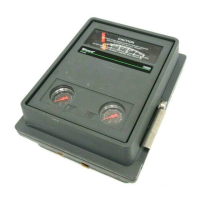
4195KA, KB, KC, and KS Controllers
Instruction Manual
Form 5207
April 2007
1-8
Table 1-4. Process Sensor (Bourdon Tube) Pressure Ratings and Materials
BOURDON TUBES
SPAN
(1)
OPERATING RANGE
(2)
OPERATING
LIMITS
(4)
STANDARD
MATERIAL
Minimum Maximum Minimum Maximum
(3)
Bar
Metric units
0 to 1.6
0 to 2.5
0 to 4
0 to 6
1
2
2
3.5
2
4
4
7
−1
−1
−1
−1
3
6
6
10
3.3
6.6
6.6
11
S31600 (316 SST)
0 to 10
0 to 16
0 to 25
0 to 40
7
10
20
20
14
20
40
40
−1
−1
0
0
20
30
60
60
22
33
66
66
0 to 60
0 to 100
0 to 160
0 to 300
55
76
160
250
70
100
200
350
0
0
0
0
90
135
270
420
103
155
310
482
Psig Psig Psig Inch Hg Psig Psig
STANDARD
MATERIAL
U.S. units
0 to 30
0 to 60
0 to 100
0 to 200
15
30
50
100
30
60
100
200
−30
−30
−30
−30
42
84
140
280
48
96
160
320
S31600 (316 SST)
0 to 300
0 to 600
0 to 1000
0 to 1500
150
300
750
1100
300
600
1000
1500
−30
0
0
0
420
840
1300
1950
480
960
1500
2250
0 to 3000
0 to 5000
2200
3700
3000
5000
0
0
3900
6000
4500
7000
1. Minimum or maximum span, or any span in between, may be positioned anywhere within the operating range. For example, if a 0 to 2 bar (0 to 30 psig) sensing element is used
and the minimum span of 1 bar (15 psig) is set, the process indication can be calibrated to a range of −1 to 0 bar (−30 inch Hg to 0 psig), 0 to 1 bar (0 to 15 psig), 1 to 2 bar (15 to 30
psig), 2 to 3 bar (27 to 42 psig) or any value between the operating range minimum and maximum values.
2. Travel stops should be used when the maximum or minimum process pressure will be 5% over or under the calibrated range. For example, a 0 to 2 bar (0 to 30 psig) sensing
element is calibrated for 0.7 to 2 bar (10 to 30 psig), the desired range. The minimum expected pressure is 0 psig and the maximum expected pressure is 2.8 bar (40 psig). Travel
stops must be used to prevent excessive overtravel and undertravel since the maximum allowable overpressure and underpressure is higher than 5% of the 1.4 bar (20 psig) span
which is ±70 mbar (±1 psig).
3. Bourdon tube without travel stops may be pressured to this value without permanent zero shift.
4. Bourdon tube with travel stops set may be pressured to this value without permanent zero shift.
Table 1-5. Optional Process Connections
INPUT RANGE CONNECTION
Bar Psig Size Material
Up to
0 to 400
Up to
0 to 5000
J 1/2 NPT external
or J 1/2 NPT
internal
J Steel or
J stainless
steel
0 to 400 to
0 to 600
0 to 5000 to
0 to 10,000
1/2 NPT internal Stainless steel
0 to 400 to
0 to 600
0 to 5000 to
0 to 10,000
1/2 NPT external Stainless steel
Table 1-6. Supply Pressure Data
OUTPUT SIGNAL
RANGE
NORMAL
OPERATING
SUPPLY
PRESSURE
(1)
MAXIMUM
PRESSURE LIMIT
(2)
Bar
0.2 to 1.0 1.4 2.8
0.4 to 2.0 2.4 2.8
Psig
3 to 15 20 40
6 to 30 35 40
1. If this pressure is exceeded, control may be impaired.
2. If this pressure is exceeded, damage to the controller may result.

 Loading...


