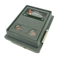
4195KA, KB, KC, and KS Controllers
Instruction Manual
Form 5207
April 2007
7-1
Section 7
Parts
Parts Ordering
Whenever corresponding with your Emerson
Process Management sales office about this
equipment, always mention the controller serial
number. When ordering replacement parts, refer to
the 11-character part number of each required part
as found in the following parts list.
WARNING
Use only genuine Fisher replacement
parts. Components that are not
supplied by Emerson Process
Management should not, under any
circumstances, be used in any Fisher
instrument. Use of components not
supplied by Emerson will void your
warranty, might adversely affect the
performance of the instrument, and
could give rise to personal injury and
property damage.
Note
Neither Emerson, Emerson Process
Management, nor any of their affiliated
entities assumes responsibility for the
selection, use, and maintenance of
any product. Responsibility for the
selection, use, and maintenance of
any product remains with the
purchaser and end-user.
Parts Kits
Description Part Number
4190 Series Auto/Manual Repair Kit
Contains keys 277, 278, 279, 281, 292,
293, 294, 298, 306, 312 R4190X0AM12
4190 Series Auto/Manual Retrofit Kit, SST tubing,
Contains keys 138, 273, 312, 313,
314, 315, 316 R4190X00S12
4190 Series Case Handle Kit
Contains lever and mounting hardware R4190X00H12
4190 Series Controller Repair Kit
Contains keys 4, 5, 7, 8, 24, 52 R4190X00C12
4190 Series Pointer and Bracket Repair Kit
Contains pointer and bracket ass’y,
three machine screws, three washers R4190X00P12
Description Part Number
4190 Series Relay Replacement Kit
Contains Relay Assembly (includes keys 13 and 15)
and key 10
0.2 to 1.0 bar (3 to 15 psig) RRELAYX83C2
0.4 to 2.0 bar (6 to 30 psig) RRELAYX83D2
Type 4195KBF Anti-Reset Windup Retrofit Kit,
SST tubing, Contains keys 44 and 55 R4190X00S22
Parts List
Abbreviations Used In Parts List
adj: adjustment
alt desgntn: alternative designation
ass’y: assembly
conn(s): connection(s)
diff: differential (as in process differential
pressure)
fdback: feedback
fill hd: fillister head (as in fillister head cap screw)
ext: external
hd: head (as in machine screw head)
int: internal
OD: outside diameter
p/o part of (as in part of another assembly)
pl: plated (as in plated steel)
pt: point (as in set point)
qty: quantity
SST: stainless steel
w/: with
w/o: without
Key Description Part Number
Controller Common Parts (figure 7-1)
Note
Figure 7-1 shows key numbers for the common
construction of all controller types. Figure 7-1
continues over several pages. Be sure to check all
pages of figure 7-1 to find the common key
numbers.
1 Case and cover ass’y
For use w/o remote set pt 46A5903X012
For use w/remote set pt 46A5902X012
2 Nameplate, A91100 (aluminum) - - -
3 Frame, A03600 (aluminum) 56A7001X012
4* Frame gasket, chloroprene
For use between frame and frame
manifold (key 135) 18A0749X012
5* Gasket, chloroprene
4195KA, KB, and KS (1 req’d)
4195KC (2 req’d) 18A0742X012
6 Machine screw, fill hd, 18−8 SST (9 req’d)
2 req’d to mount the prop band ind cover
to the frame
4 req’d to mount bellows bracket
(key 31) to bellows beam (key 49)
2 req’d to attach process scale
brackets (keys 376, 377) to frame 1P4373X0012
*Recommended spare parts

 Loading...


