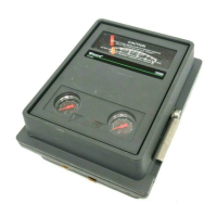
4195KA, KB, KC, and KS Controllers
Instruction Manual
Form 5207
April 2007
5-2
C0528-1/IL
BOURDON
TUBE
PROCESS
INDICATOR
PROCESS
INDICATOR
CONNECTING
LINK
SET POINT
ADJUSTMENT
INDICATOR
ZERO ADJUSTMENT
ZERO ADJUSTMENT
LOCKING SCREW
PROCESS
SPAN ADJUSTMENT
OUTPUT PRESSURE
GAUGE
PROPORTIONAL
BAND INDICATOR
COVER
PROPORTIONAL
BAND ADJUSTMENT
SUPPLY PRESSURE
GAUGE
ZERO
ADJUSTMENT
LOCKING SCREW
INDICATOR
ZERO
ADJUSTMENT
TIE BAR
LINEARITY
ADJUSTMENT
PROCESS
SPAN
ADJUSTMENT
LINK 5
LINK 1
SHORT
PIVOT
ASSEMBLY
LONG PIVOT
ASSEMBLY
BI METAL STRIP FOR
TEMPERATURE COMPENSATION
SENSING ELEMENT CAN ALSO BE A CAPSULAR ELEMENT
FRONT VIEW OF CONTROLLER WITH
BOURDON TUBE PROCESS SENSOR
CAPSULAR ELEMENT
PROCESS SENSOR
NOTE:
Figure 5-1. 4195KS Series Controller Parts and Adjustments Locations
Prestartup Checks for 4195KS Series
Controllers
When performing the checks, open loop conditions
must exist. Refer to figure 5-1 for location of
adjustments.
Note
If the controller has the auto/manual
option (option E), be sure the
controller is in the automatic mode
prior to performing prestartup checks.
1. Connect supply pressure to the supply pressure
regulator, and be sure it is delivering the proper
supply pressure to the controller. Provide a means
of measuring the controller output pressure.
2. For controllers with remote set point (option M),
connect regulated pressure of 0.2 to 1.0 bar (3 to 15
psig) or 0.4 to 2.1 bar (6 to 30 psig) to the remote
set point connection at the top of the controller case.
3. Loosen two screws (key 6), lift off the
proportional band cover (key 36), and set the
proportional band knob between DIRECT and
REVERSE.
4. The process indicator should indicate the process
pressure. For example, with the process pressure at
50 percent of the input span, the process pointer
should be 50 percent (+/-1 percent) of its span.
Slight adjustment of the indicator zero screw may be
necessary. See figure 5-1 for zero adjustment and
locking screw location.
5. If desired, the accuracy can be verified at other
points on the scale. If the indicator appears to be out
of calibration, refer to the process zero and span
adjustment portion of the calibration procedure.
6. Install the proportional band cover and install two
screws (key 6).
Startup for 4195KS Series Controllers
It is recommended that the controller switching
points be set as described in the calibration
procedures.

 Loading...


