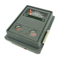
4195KA, KB, KC, and KS Controllers
Instruction Manual
Form 5207
April 2007
5-3
C0528-1/IL
SCREW 1
SCREW 3
SCREW 2
SIDE VIEW OF
CONTROLLER SHOWING
FLAPPER LEVELING SCREWS
PROCESS
SPAN
ADJUSTMENT
REMOTE SET POINT
SPAN ADJUSTMENT
SIDE VIEW OF
SET POINT/PROCESS
INDICATOR ASSEMBLY
Figure 5-1. 4195KS Series Controller Parts and Adjustments Locations (continued)
If they are used, slowly open the upstream and
downstream manual control valves in the pipeline
and close the manual bypass valve.
Calibration of 4195KS Series
Controllers
Note
Some of the following procedures
require that the proportional band
knob be adjusted to between DIRECT
and REVERSE. If this is done, it will
be necessary to set the proportional
band knob to 400 (direct or reverse
action) before replacing the
proportional band indicator cover.
If the prestartup checks revealed faulty adjustment
of the process indicator, perform the calibration
procedures. These procedures are valid for either
shop or field calibration, provided that open process
loop conditions exist.
Note
If the controller has the auto/manual
option, be sure the controller is in the
automatic mode prior to performing
the calibration procedures.
Process Zero and Span Adjustment
Note
Any adjustment of the pointer span
adjustment screw will require
readjustment of the pointer zero
adjustment screw.
1. Refer to figure 5-1 for location of adjustments.
2. Remove the two screws (key 6) and lift off the
proportional band indicator cover (key 36).
3. Set the proportional band between DIRECT and
REVERSE.
4. Adjust the process pressure to the low limit of the
input range.
5. Adjust the process pointer to the lowest limit of
the input scale by loosening the zero adjustment
locking screw and turning the zero adjustment
screw.
6. Adjust the process pressure to the upper limit of
the input span. Note whether the pointer indication is
above or below the upper limit of the process scale.

 Loading...


