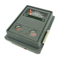
4195KA, KB, KC, and KS Controllers
Instruction Manual
Form 5207
April 2007
6-34
Capsular Element Controller Zero and Span
Adjustment
Note
For routine zero and span calibration,
refer to the appropriate procedures in
Section 3, 4, or 5. Use the following
maintenance zero and span
adjustment procedure only if difficulty
is encountered with the routine
procedure or if nonlinearity occurs.
Provide a means of applying process pressure to the
sensing element and a regulated supply pressure
adjusted to the normal operating pressure (see table
1-6). Plug the controller output or connect it to a
gauge. Monitoring the controller output is not
necessary. However, the flapper should not contact
the nozzle at any time while performing this
procedure. If it does, adjust flapper screw 2 (the one
nearest the nozzle) to provide clearance. Refer to
figure 6-19 for the adjustment locations. Refer to
figure 7-1 for the key number locations.
Note
Any adjustment of the process pointer
span adjustment screw requires
readjustment of the process pointer
zero adjustment screw.
1. Remove the two machine screws (key 6) and lift
off the proportional band indicator cover (key 36).
2. Set the proportional band between DIRECT and
REVERSE.
3. Adjust the reset (4195KB and KC Series only) to
0.01 minutes per repeat.
4. Adjust the rate (4195KC Series only) to OFF.
5. For a controller with manual set point, move the
set point indicator to the mid-scale mark on the
process scale. For a controller with remote set point,
adjust the remote set point pressure until the set
point indicator is at the mid-scale mark on the
process scale.
6. Apply process pressure equal to the mid-scale
value of the process scale span.
7. The process pointer should be aligned with the
pointer subassembly as shown in figure 6-15. If not,
loosen the zero adjustment locking screw and adjust
the zero adjustment screw to align the process
pointer with the pointer subassembly. Tighten the
zero adjustment locking screw.
8. The process pointer should indicate mid-scale ±3
percent of the process scale span. If not, loosen the
screw on either link 1 or link 5 and adjust the length
so that the process pointer points to the mid-scale
mark on the process scale. Tighten the screw.
9. Apply process pressure equal to the process
scale lower limit.
10. The process pointer should indicate the process
scale lower limit. If not, loosen the zero adjustment
locking screw and adjust the zero adjustment screw
until the process pointer indicates the lower limit.
Tighten the zero adjustment locking screw.
11. Apply process pressure equal to the process
scale upper limit.
12. The process pointer should indicate the process
scale upper limit. If not, proceed as follows:
a. If the pointer indicates less than the process
scale upper limit, rotate the pointer span
adjustment clockwise to increase the span.
Adjust the span adjustment screw to correct for
one-half of the error.
b. If the pointer indicates greater than the
process scale upper limit, rotate the pointer span
adjustment counterclockwise to decrease the
span. Adjust the span adjustment screw to
correct for one-half of the error.
13. Repeat steps 9 through 12 until the zero and
span indications are within ±1 percent of the scale
limits with no further adjustment. If proper span is
achieved, proceed to step 16. If the span adjustment
screw is adjusted to its limit and the span is still too
short or too long, proceed with step 14.
14. Within the process pointer subassembly, there
are three holes for the connection of link 1. Use
procedure (a.) or (b.) below to make the coarse
span adjustment with link 1.
a. If the span is short (process pointer indication
is less than the process scale upper limit),
disconnect link 1 from the process pointer
subassembly, move the link to the lowest hole
(the hole nearest the pointer pivot), and return to
step 9. If the link is already in the lowest hole,
proceed to step 15.
b. If the span is long, (process pointer indication
is greater than the process scale upper limit),
disconnect link 1 from the process pointer
subassembly, move the link to the highest hole
(the hole furthermost from the pointer pivot), and
return to step 9. If the link is already in the
highest hole, proceed to step 15.

 Loading...


