FloBoss 107 Instruction Manual
Revised June-2017 General Information 1-3
calculations in memory, which can then be and can be communicated to
an external device either on demand or periodically.
The FB107 design allows you to configure specific applications,
including those requiring logic and sequencing control using a Function
Sequence Table (FST).
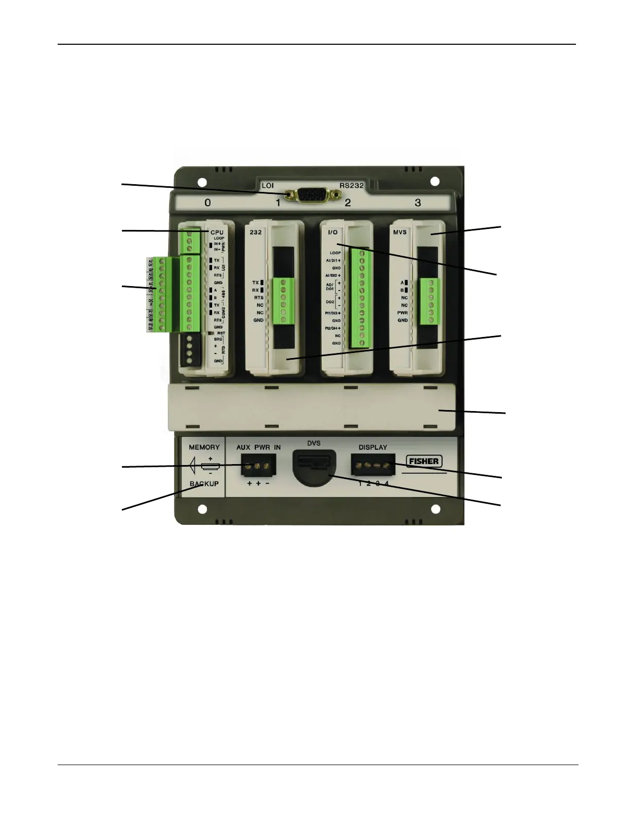
Local (LOI) Communication Port
Memory Backup Battery Connector
Slot 3 = I/O or MVS module
Slot 2 = I/O, MVS module, or COM module (COM2)
Slot 1 = I/O, MVS, or COM module (COM3)
Integral Sensor Connector
Figure 1-1. FloBoss 107 Base Unit
 Loading...


