EasyManua.ls Logo

Emerson Liebert eXM - Liebert Power Module Assembly; Figure 3 Cabinet Arrangement; Figure 4 Liebert Power Module Assembly Indicators and Controls

Emerson Liebert eXM
92 pages
To Next Page IconTo Next Page
To Previous Page IconTo Previous Page
Loading...
Installation
13 Liebert
®
eXM
Figure 3 Cabinet arrangement
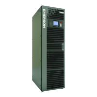
2.7 Liebert Power Module Assembly
Figure 4 Liebert power module assembly indicators and controls
The BATTERY START button allows starting the UPS on battery; refer to 7.3 - UPS Battery Start.
The Run LED is illuminated Green when the Liebert power module assembly is operating normally.
Liebert
eXM
Bypass
Distribution
Cabinet
or
Maintenance
Bypass
Cabinet
Bypass
Distribution
Cabinet
or
Maintenance
Bypass
Cabinet
Liebert
eXM
Battery
Cabinet
Battery
Cabinet
Liebert
eXM
Battery
Cabinet
Liebert eXM connected only
to Liebert BDC/MBC
(The Liebert BDC/MBC must be on right
side of the Liebert eXM)
Liebert eXM connected to Liebert BDC/MBC and Battery Cabinets
(BDC/MBC must be on right side of the Liebert eXM)
(Battery Cabinets must be on the left side of the Liebert eXM)
ALL UNITS VIEWED FROM ABOVE
Liebert eXM connected to Battery Cabinet
(Battery Cabinets must be on the left side
of the Liebert eXM)
Layouts shown are typical.
Not all auxiliary cabinets are
shown. Refer to the submittal
drawings for the exact
configuration of your system.
Ready Switch
DIP Switches
Run LED
Fault LED
Battery Start Button

Table of Contents

Related product manuals