Installation Drawings
Liebert
®
eXM
™
34
4.0 INSTALLATION DRAWINGS
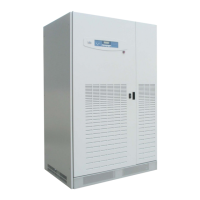
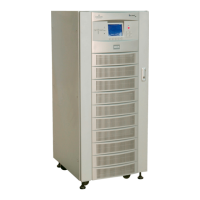
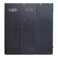
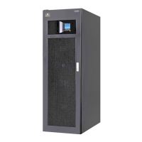
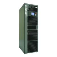
The diagrams in this section illustrate the key mechanical and electrical characteristics of the Liebert
eXM UPS System cabinets (UPS, Liebert BDC and battery).
Figure 20 UPS dimensions—Front view
NOTES
1. Dimensions are in inches (mm)
2. 24" (610mm) minimum clearance above unit and
12" (305mm) rear clearance required for air exhaust.
36" (914mm) front access required for service
3. Keep cabinet within 15 degrees of vertical.
4. Top and bottom cable entry available through removable
access plates. Remove, punch to suit conduit size and replace.
5. Unit bottom is structurally adequate for forklift handling.
6. Control wiring and power wiring must be run in separate conduits.
7. Copper cables only are recommended.
8. All wiring is to be in accordance with national and local
electrical codes.
9. All battery cabinets must be positioned on the left side
of the UPS.
10. Battery cabinets offered at 600mm and 880mm widths.
23.6" (600mm)
78.7"
(2000mm)
FRONT VIEW
 Loading...
