9. Install the gland body into the conduit opening on the core processor housing.
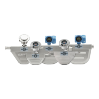
10. Insert the wires through the gland body and tighten the gland nut onto the gland
body.
A. Shield folded back
B. Gland body
4.2.5 Connect the wires to the core processor terminals
After the 4-wire cable has been prepared and shielded (if required), connect the individual
wires of the 4-wire cable to the terminals on the core processor.
Procedure
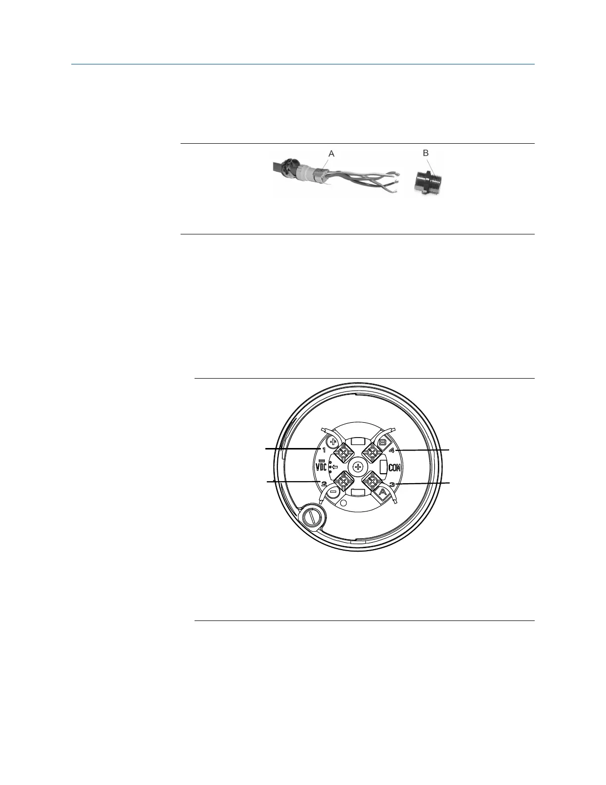
1. Connect the wires to the core processor terminals.
• If you are connecting to a standard core processor, use the following image and
connections:
A. Terminal 1 (Power supply +): Red wire
B. Terminal 2 (Power supply -): Black wire
C. Terminal 3 (RS-485/A): White wire
D. Terminal 4 (RS-485/B): Green wire
• If you are connecting to an enhanced core processor, use the following image
and connections:
Installation Manual Transmitter power and I/O wiring
20002158 October 2021
Installation Manual 33

 Loading...