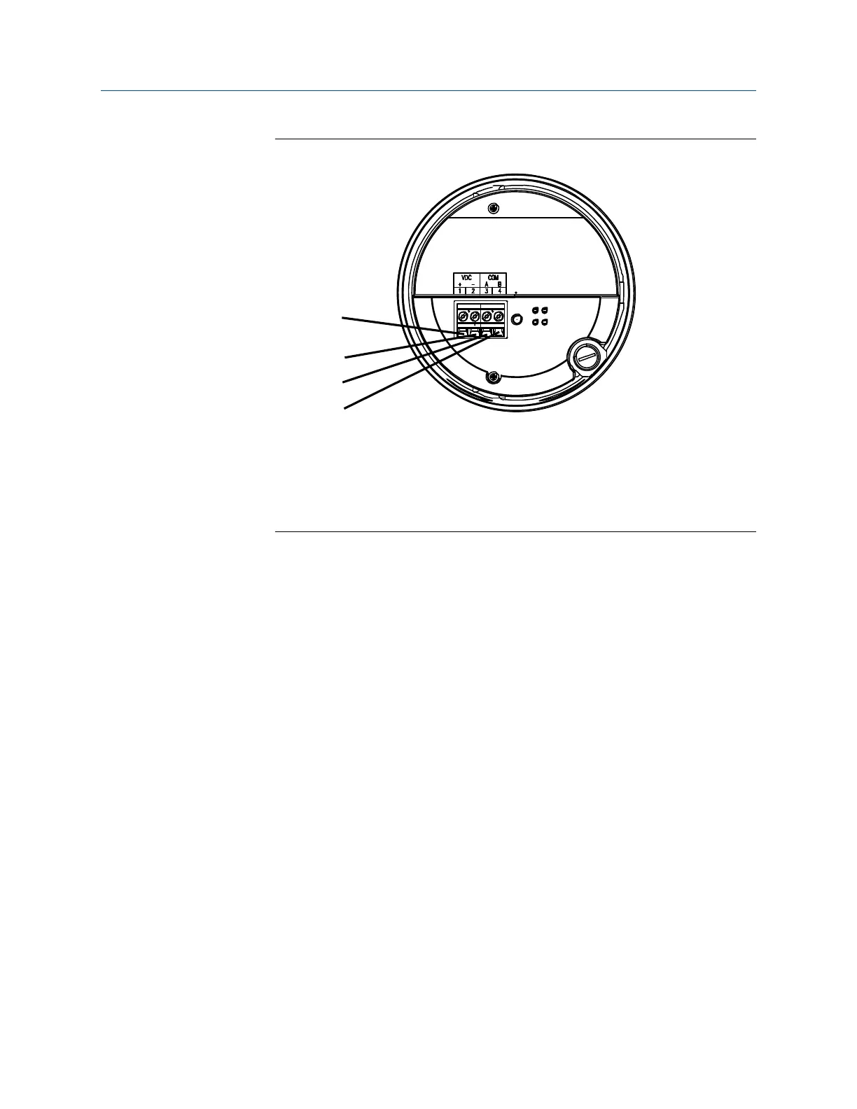
A. Terminal 1 (Power supply +): Red wire
B. Terminal 2 (Power supply -): Black wire
C. Terminal 3 (RS-485/A): White wire
D. Terminal 4 (RS-485/B): Green wire
2. Reinstall the core processor cover.
3. Torque the cover screws to:
• For aluminum housing: 10 in lbf (1.13 N m) to 13 in lbf (1.47 N m)
• For stainless steel housing: minimum 19 in lbf (2.15 N m)
If properly seated, there will be no gap between cover and base.
4. Connect the wires to the transmitter terminals using the transmitter installation
manual.
4.3 Connect the 9-wire cable
Procedure
1. Prepare and install the cable according to the instructions in the Micro Motion 9-Wire
Flow Meter Cable Preparation and Installation Guide.
2. Insert the stripped ends of the individual wires into the terminal blocks of the
junction box. Ensure that no bare wires remain exposed.
3. Match the wires color for color. For wiring at the transmitter or remote core
processor, refer to the transmitter documentation.
4. Tighten the screws to hold the wires in place.
5. Ensure integrity of gaskets, then tightly close and seal the junction box cover and all
housing covers.
6. Refer to the transmitter installation manual for signal and power wiring
instructions.
Transmitter power and I/O wiring Installation Manual
October 2021 20002158
34 Micro Motion ELITE

 Loading...