17
Safety Manual
00809-0200-5100, Rev GB
Installation and Configuration
February 2017
Installation and Configuration
The basic principles of SIL alarm relay output for the Rosemount Tank Gauging Safety System is
illustrated in Figure 4-5 on page 17 and Figure 4-6 on page 18. These illustrations show two
configuration examples for a SIL 3 and a SIL 2 system, respectively.
Figure 4-5. SIL Alarm relay output for a 5900 (2-in-1) complying with SIL 3
+-
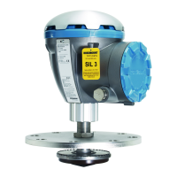
Rosemount 2410
Rosemount 5900 (2-in-1)
SIL Alarm triggered by one or
more of:
SIL High/Low Alarm
Internal error
Not configured
Not approved
Rosemount 2410
Rosemount 5900 (2-in-1)
SIL Alarm Relay output to
emergency shut-down system
SIL Alarm Relay output to
emergency shut-down system
Ta nk bus
Ta nk bus
SIL Alarm
SIL Alarm
SIL Alarm
Relay
SIL Alarm
Relay
 Loading...


