Emerson Process Management GmbH & Co. OHG2-8
X-STREAM XE
Short Form Manual
HASXEE-SFM-HS
05/2017
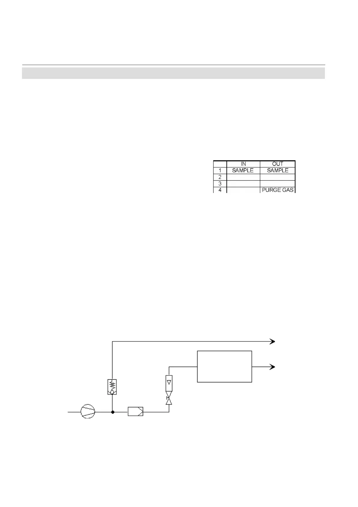
Pressure control valve
Flow sensor
Exhaust
Exhaust
Analyzer
Sample gas pump
Filter
Fig. 2-2: Labelling of Gas Connectors (example)
The analyzer should be mounted close to the
sample gas source to minimize transport time.
A sample gas pump can be used to reduce the
reaction time; this requires the analyzer to be
operated in bypass mode or to be tted with
a pressure control valve to protect against
excessive gas ow and pressure (Fig. 2-3).
The number of gas connections and their
conguration may vary according to analyzer
version and installed options.
All gas connectors are labelled and can be
found on the
•
analyzer’s rear panel (X-STREAM XEGP,
X-STREAM XEGK)
• underside of the analyzer (X-STREAM eld
housings)
Should it be necessary to open the gas lines,
the gas connectors should be sealed with
PVC caps to prevent pollution by moisture,
dust, etc.
Fig. 2-3: Installation in Bypass Mode
2.5 Installation - Gas Connections

 Loading...


