Safety
Information
Introduction
Product
information
System
design
Mechanical
installation
Electrical
installation
Getting
started
Optimisation Parameters
Technical
data
Component
sizing
Diagnostics
Unidrive SP Regen Installation Guide 11
Issue Number: 2 www.controltechniques.com
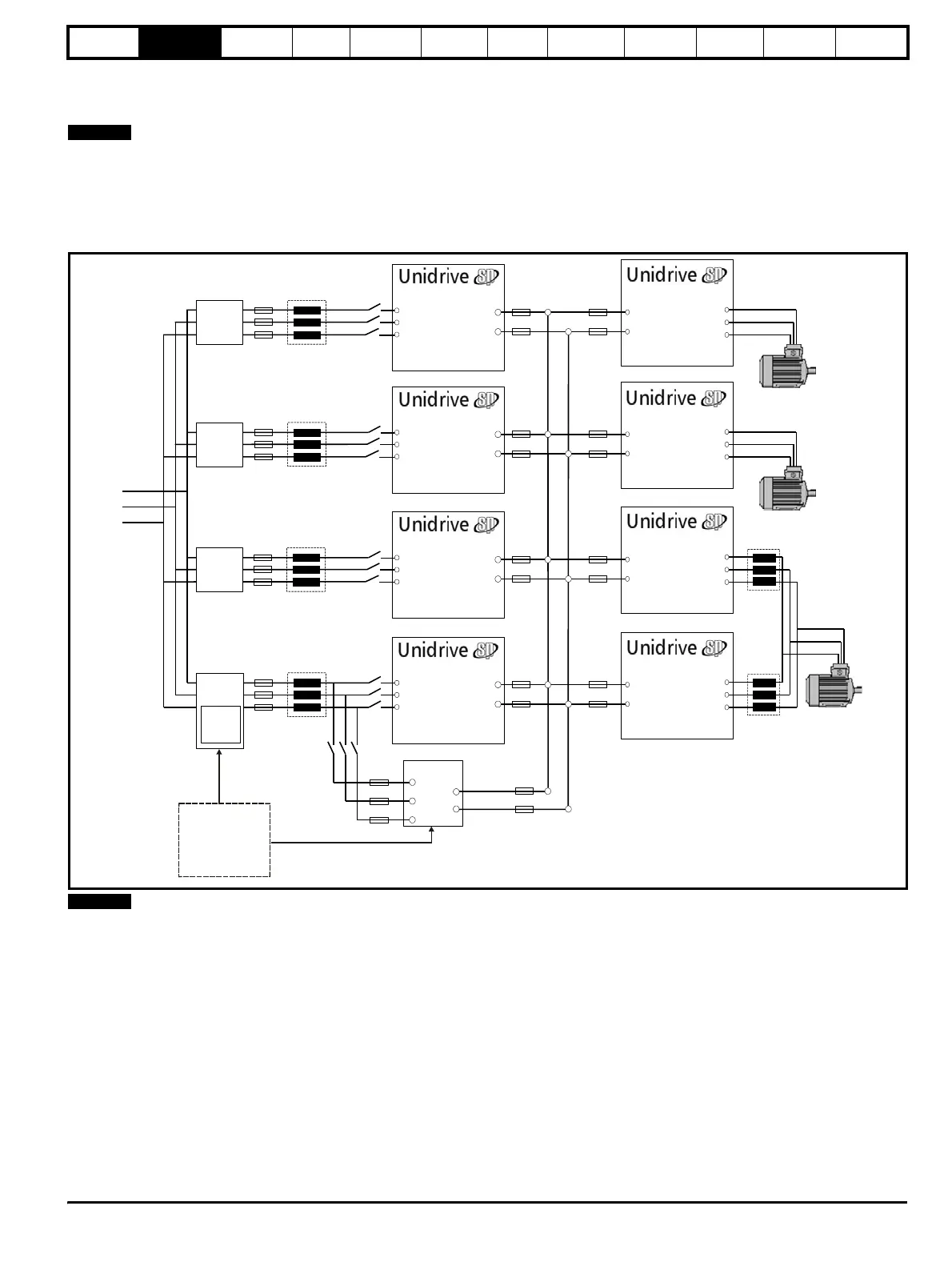
2.8.3 Multiple Regen, multiple motoring system
Figure 2-5 shows a multiple regen drive system with multiple motoring drives. For this configuration the regen drives are sized to the total power
requirement of all motoring drives.
For the multiple regen and multiple motoring drives arrangement there are two possible options for the required start-up circuit. This can either consist
of a Unidrive SPMC rectifier module (for example an SPMC 1402 is capable of charging a maximum DC Bus capacitance of 66mF) or an external
charging resistor as detailed in Chapter 4 System design on page 30.
Special care should be taken when designing a multiple regen and multiple motoring drive system ensuring that all the required fusing is in place on
both the common DC Bus connections and the AC supply to all regen drives.
Figure 2-5 Multiple Regen, multiple motoring system
All drives paralleled must be of the same frame size, and a derating also
applies as specified in Chapter 3 Product Information on page 12
NOTE
DC Bus
Connections
U
V
W
Motor
Connection
-DC
+DC
U
V
W
Motor
Connection
-DC
+DC
U
V
W
Motor
Connection
-DC
+DC
U
V
W
Motor
Connection
-DC
+DC
U
V
W
Regen Drive
-DC
+DC
U
V
W
Regen Drive
-DC
+DC
U
V
W
Regen Drive
-DC
+DC
U
V
W
Regen Drive
-DC
+DC
-DC
+DC
L3
L2
L1
SPMC
Additional
Circuitry
Additional
Circuitry
Additional
Circuitry
Additional
Circuitry
External
charging
circuit
L1
L2
L3
Motoring Drive
Motoring DriveMotoring Drive
Motoring DriveMotoring DriveMotoring DriveMotoring Drive
Motoring Drive
Charging circuit can
consist of either
Unidrive SPMC
solution or external
charging circuit
(Unidrive SPMC
recommended)
NOTE