Safety
Information
Introduction
Product
information
System
design
Mechanical
installation
Electrical
installation
Getting
started
Optimisation
Parameters
Techn i cal
data
Component
sizing
Diagnostics
Unidrive SP Regen Installation Guide 175
Issue Number: 2 www.controltechniques.com
To enable the PID controller the drive must be healthy (Pr 10.01 = 1) and the PID enable (Pr 14.08) must be one. If the option enable source
(Pr 14.09) is 00.00 or routed to a non-existent parameter the PID controller is still enabled provided Pr 10.01 = 1 and Pr 14.08 = 1. If the optional
enable source (Pr 14.09) is routed to an existing parameter the source parameter must be one before the PID controller can be enabled. If the PID
controller is disabled the output is zero and the integrator is set to zero.
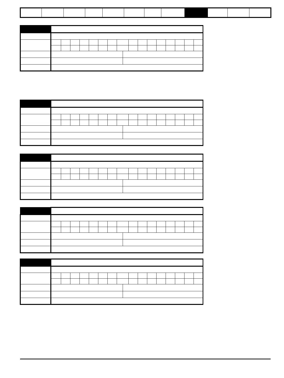
14.09 PID optional enable source
Drive mode Regen
Coding
Bit SP FI DE Txt VM DP ND RA NC NV PT US RW BU PS
2 1111
Range Regen Pr 0.00 to Pr 21.51
Default Regen Pr 0.00
Update rate Background
14.10 PID P gain
Drive mode Regen
Coding
Bit SP FI DE Txt VM DP ND RA NC NV PT US RW BU PS
3 111
Range Regen 0.000 to 4.000
Default Regen 1.000
Update rate Background
14.11 PID I gain
Drive mode Regen
Coding
Bit SP FI DE Txt VM DP ND RA NC NV PT US RW BU PS
3 111
Range Regen 0.000 to 4.000
Default Regen 0.500
Update rate Background
14.12 PID D gain
Drive mode Regen
Coding
Bit SP FI DE Txt VM DP ND RA NC NV PT US RW BU PS
3 111
Range Regen 0.000 to 4.000
Default Regen 0.000
Update rate Background
14.13 PID upper limit
Drive mode Regen
Coding
Bit SP FI DE Txt VM DP ND RA NC NV PT US RW BU PS
2 111
Range Regen 0.00 to 100.00 %
Default Regen 100.00
Update rate Background