Safety
Information
Introduction
Product
information
System
design
Mechanical
installation
Electrical
installation
Getting
started
Optimisation Parameters
Technical
data
Component
sizing
Diagnostics
34 Unidrive SP Regen Installation Guide
www.controltechniques.com Issue Number: 2
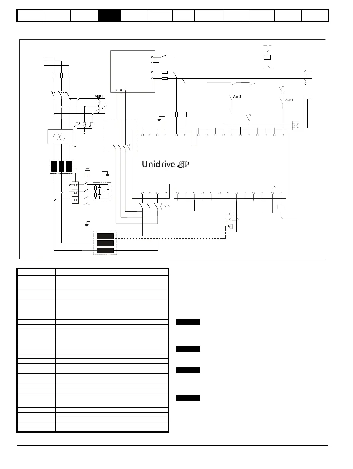
4.2.2 Single Regen, multiple motoring system using a Unidrive SPMC
Figure 4-2 Power connections: Single Regen, multiple motoring system
Table 4-2 Key to Figure 4-3 Figure 4-2 shows both the power and control connections for the
multiple motoring regen solution. For the multiple motoring system an
external charging circuit is required due to the additional capacitance
from the multiple motoring drives. The external charging circuit is
interlocked with the Regen drive enable to prevent operation with this
circuit still connected.
In this example, the external charging circuit consists of a Unidrive SPMC
module. Refer to section 3.5 Unidrive SPMC half controlled thyristor
rectifier on page 19 for further details of the Unidrive SPMC.
For the multiple motoring drive solution, the Regen drive and associated
Unidrive SPMC must be sized to the total power requirements of all
motoring drives.
The regen inductor duty is very arduous and therefore selection is critical.
As a result only regen inductors specified in this guide should be used.
Fusing F4, F5, F6 are only required where fusing F1, F2, F3 exceed
these. For example in a multiple regen drive system, where F1, F2, F3
equal total system current rating.
The SPMC uses the regen inductor as line reactors. The SPMC may be
powered from the incoming supply using a standard line reactor if
required.
UVW
L1 L2 L3 PE
-DC +DC
-DC
+DC
21
1
2 3 4 5 6 7 8 9 10 11 41 42
22 23 24 25 26 27 28 29 30 31
K2
L2
RFI
F1 F2 F3
VDR2
VDR3
VDR4
VDR5
VDR6
Tc.1
L1
L2
L3
AC Supply
Connections
Motoring
drive DC
Connections
+24 output
Enable motor drive
Contactor closed
0common
Drive enable
C1
OPD1
Aux.1
T. 30
T. 24
Rly.1
optional
L1
Regen drive
S1
K1
Aux.2a
Unidrive
SPMC
L1
L2
L3
85
84
+DC
-DC
F12
F11
+24Vdc external supply
0V common
Regen inductor
thermistor
0V common
V
V
Aux.3
K3
K2
AC Supply
Connections
NOT USED
S6
Drive healthy
Reset input
Contactor
control
F13
F14
K3
Vsupply
Aux.2b
Aux.2c
Charging
branch
circuit
2a 2b 2c
Aux
Vsupply
Key Description
L1, L2, L3 Three phase supply
F1, F2, F3 Main regen system supply fuses
VDR1, VDR2, VDR3 Varistor network line-to-line
VDR4, VDR5, VDR6 Varistor network line-to-ground
F7, F8, F9, F10
DC bus fusing to motoring drive
F11, F12
DC bus fusing to Regen drive
F13, F14
SPMC DC fuse protection
RFI Optional RFI filter
C1 Switching frequency filter capacitor
L1 Switching frequency filter inductor
L2 Regen inductor
K1 Main supply contactor
K2 Regen drive main contactor
K3 Charging contactor
OPD1 Overload protection device for C1
Aux.1 OPD NO auxiliary contact
Aux.2a K2 NO auxiliary contact
Aux.2b K2 NC auxiliary contact
Aux.2c NC auxiliary for SPMC (optional)
Aux.3 K3 NC auxiliary contact
Rly.1
Optional isolation for enable between Regen and motoring drive(s)
Mt.1 Motor thermistor 1
Mt.2 Motor thermistor 2
Tc.1 Regen inductor thermistor
+DC, -DC Motoring drive power connection to Regen drive
S1 Regen drive enable
S2 Motoring drive enable
S3 Motoring drive reset
S4 Motoring drive run forward
S5 Motoring drive run reverse
S6 Regen drive reset input (Pr 8.24 = Pr 10.33)
Vsupply System control supply
NOTE
NOTE
NOTE
NOTE