Safety
Information
Introduction
Product
information
System
design
Mechanical
installation
Electrical
installation
Getting
started
Optimisation
Parameters
Technical
data
Component
sizing
Diagnostics
178 Unidrive SP Regen Installation Guide
www.controltechniques.com Issue Number: 2
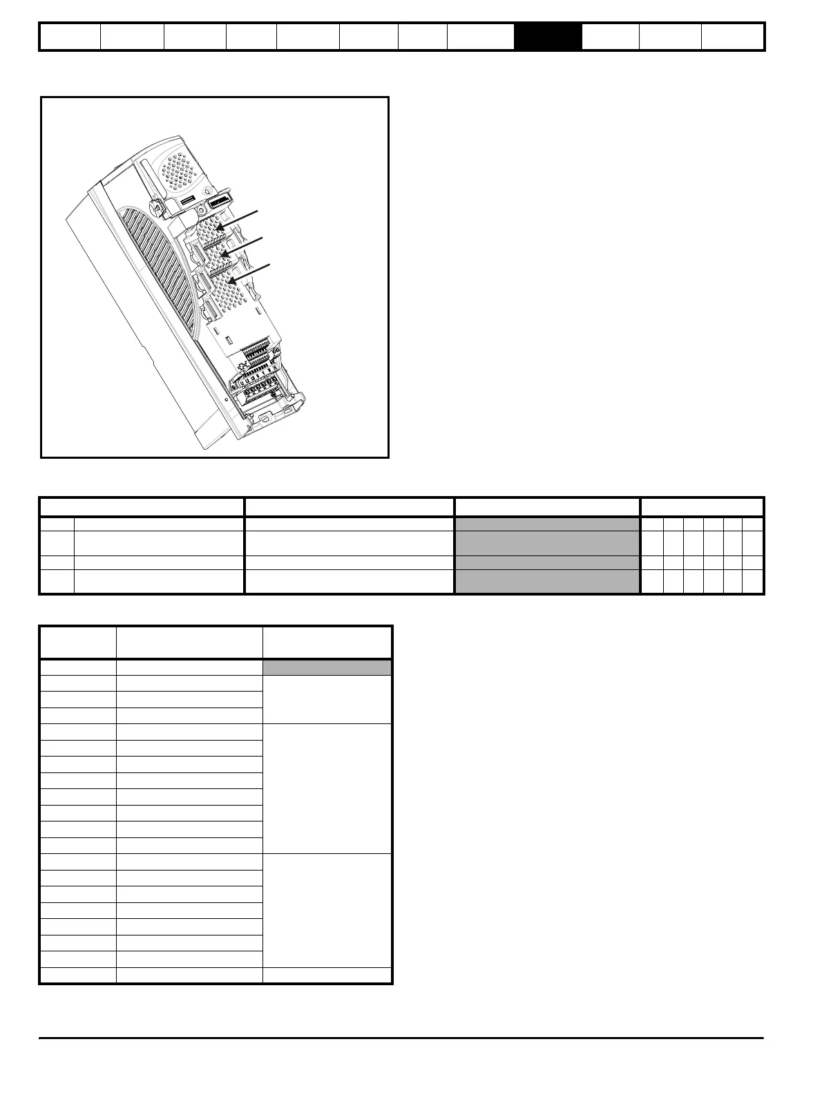
9.14 Menus 15, 16 and 17: Solutions Module set-up
Figure 9-12 Location of Solutions Module slots and their corresponding menu numbers
9.14.1 Parameters common to all categories
The Solutions Module ID indicates the type of module that is fitted in the corresponding slot.
For full parameter descriptions for Menus 15, 16 and 17, refer to the Unidrive SP Advanced User Guide or the individual Solutions Module User
Guide.
Parameter
Range(
Ú) Default(Ö)
Type
x.01 Solutions Module ID 0 to 499 RO Uni PT US
x.02
Solutions Module software
version
0.00 to 99.99
RO Uni NC PT
x.50 Solutions Module error status 0 to 255 RO Uni NC PT
x.51
Solutions Module software
sub-version
0 to 99
RO Uni NC PT
Solutions
Module ID
Module Category
0 No module fitted
101 SM-Resolver
Feedback102 SM-Universal Encoder Plus
104 SM-Encoder Plus
201 SM-I/O Plus
Automation
203 SM-I/O Timer
204 SM-PELV
206 SM-I/O 120V
207 SM-I/O Lite
301 SM-Applications
302 SM-Applications Lite
303 SM-EZMotion
403 SM-PROFIBUS-DP
Fieldbus
404 SM-Interbus
406 SM-CAN
407 SM-DeviceNet
408 SM-CANopen
409 SM-SERCOS
410 SM-Ethernet
501 SM-SLM SLM
Solutions Module
slot 1 (Menu 15)
Solutions Module
slot 2 (Menu 16)
Solutions Modul
slot 3 (Menu 17)