Safety
Information
Introduction
Product
information
System
design
Mechanical
installation
Electrical
installation
Getting
started
Optimisation Parameters
Technical
data
Component
sizing
Diagnostics
Unidrive SP Regen Installation Guide 39
Issue Number: 2 www.controltechniques.com
-DC
+DC
F19
F20
UVW
L1 L2 L3 PE
-DC +DC
21
1
2 3 4 5 6 7 8 9 10 11 41 42
22 23 24 25 26 27 28 29 30 31
T.30
T.24
S5
Mt.1
AC Supply
Connections
NOT USED
Connections
Motoring
drive DC
Connections
U
V
W
PE
S2
S3 S4
Drive enable
0V common
Drive reset
Run forward
Run reverse
Motor thermistor
0V common
Motoring drive
F21
F22
UVW
L1 L2 L3 PE
-DC +DC
21
1
2 3 4 5 6 7 8 9 10 11 41 42
22 23 24 25 26 27 28 29 30 31
S5
Mt.2
AC Supply
Connections
NOT USED
Connections
Motoring
drive DC
Connections
U
V
W
PE
S2
S3 S4
Drive enable
0V common
Drive reset
Run forward
Run reverse
Motor thermistor
0V common
Motoring drive
+24V output
+24V output
Motor
Motor
Drive healthy
Drive healthy
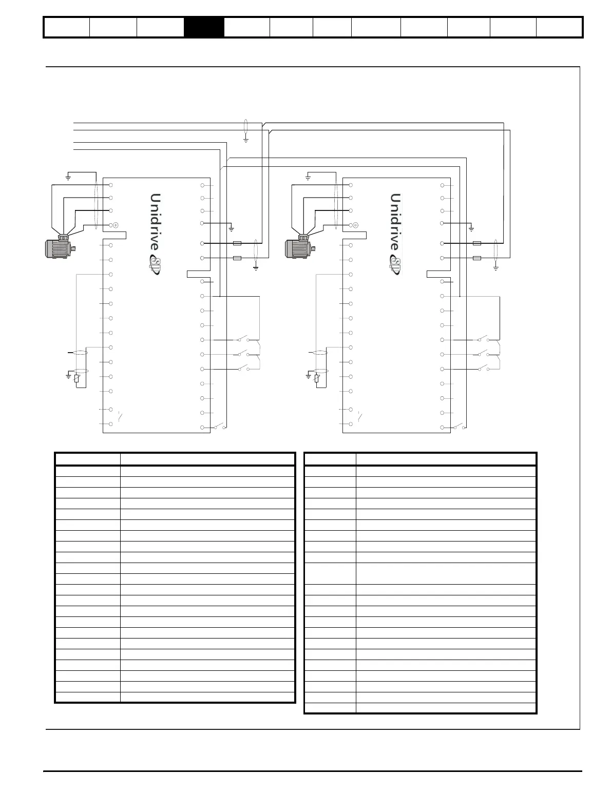
Table 4-4 Key to Figure 4-4
Key Description Key Description
L1, L2, L3 Three phase supply Aux.1 OPD1 NO auxiliary contact
F1, F2, F3 Main regen system supply AC fuses Aux.2 OPD2 NO auxiliary contact
F4, F5, F6 Regen drive 1 AC fuses Aux.2a K2 NO auxiliary contact regen 1
F7, F8, F9 Regen drive 2 AC fuses Aux.2b K2 NC auxiliary contact regen 1
F10, F11, F12 SPMC AC fusing Aux.2c K2 NC auxiliary contact regen 1
F13, F14 DC Bus fusing to SPMC Aux.3 K3 NC auxiliary contact
F15, F16, F17, F18 DC Bus fusing to regen drives Aux.4a K4 NO auxiliary contact regen 2
F19, F20, F21, F22 DC Bus fusing to motoring drive Aux.4b K4 NC auxiliary contact regen 2
VDR1, 2, 3 Varistor network line-to-line Aux.4c K4 NC auxiliary contact regen 2
VDR4, 5, 6 Varistor network line-to-ground
Rly.1
Optional isolation for enable between Regen and
motoring drive(s)
RFI Optional RFI filter
L1 Switching frequency filter inductor Mt.1 Motor thermistor 1
L2 Regen inductor (regen 1) Mt.2 Motor thermistor 2
L3 Regen inductor (regen 2) Tc.1 Regen inductor thermistor
C1 Switching frequency filter capacitor (regen 1) Tc.2 Regen inductor thermistor
C2 Switching frequency filter capacitor (regen 2) +DC, -DC Motoring drive power connection to Regen drive
K1 Main supply contactor S1 Regen drive enable
K2 Regen drive 1 main contactor S2 Motoring drive enable
K3 Charging contactor S3 Motoring drive reset
K4 Regen drive 2 main contactor S4 Motoring drive run forward
OPD1 Overload protection device for C1 S5 Motoring drive run reverse
OPD2 Overload protection device for C2 S6 Regen drive reset (user programmed)
Vsupply System control supply