Safety
information
Product
information
Mechanical
installation
Electrical
installation
Getting
started
Basic
parameters
Running the
motor
Optimization NV Media Card
Advanced
parameters
Diagnostics UL Listing
14 Unidrive M100 / M101 Control User Guide
Issue Number: 1
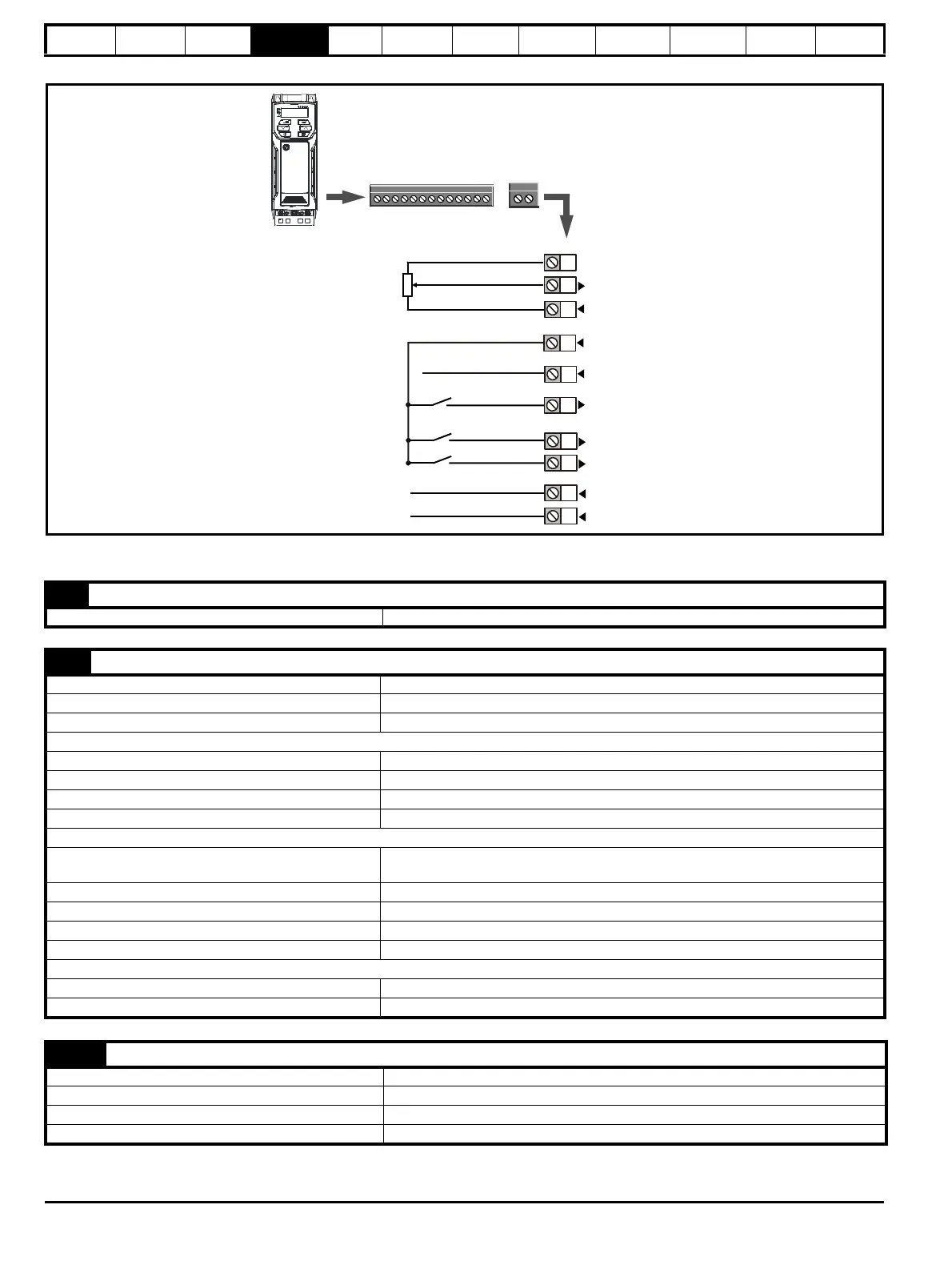
Figure 4-2 Default terminal functions
4.2.2 Control terminal specification
Relay
(over-voltage
category II)
Drive OK
Analog
frequency
reference 1
1
4
2
0V common
+10 V
12
13
At zero frequency
Run forward
Run reverse
9
10
11
Drive enable
+24 V
1 0V common
Function Common connection for all external devices
2 Analog input 1
Default function Frequency reference
Type of input Unipolar single-ended analog voltage or unipolar current
Mode controlled by… Pr 07.007
Operating in voltage mode (default)
Full scale voltage range 0V to +10 V ±3 %
Maximum offset ±30 mV
Absolute maximum voltage range -18 V to +30 V relative to 0V
Input resistance 100 k
Operating in current mode
Current ranges
0 to 20 mA ±5 %, 20 to 0 mA ±5 %,
4 to 20 mA ±5 %, 20 to 4 mA ±5 %
Maximum offset 250 µA
Absolute maximum voltage (reverse bias) -18 V to +30 V relative to 0V
Absolute maximum current 25 mA
Equivalent input resistance 165
Common to all modes
Resolution 11 bits
Sample rate 4 ms
4 +10 V user output
Default function Supply for external analog devices
Nominal voltage 10.2 V
Voltage tolerance ±3 %
Maximum output current 5 mA

 Loading...


