Unidrive M702 Getting Started Guide 35
Issue Number: 4
Safety information Product information
Mechanical
installation
Electrical
installation
Getting started
Basic parameters
(Menu 0)
Running the motor
NV Media Card
Operation
Further information
UL listing
information
4.4 Ground connections
The drive must be connected to the system ground of the AC supply. The ground wiring must
conform to local regulations and codes of practice. For further information on ground cable sizes,
refer to Table 2-5 Protective ground cable ratings on page 12.
On size 3 and 4, the supply and motor ground connections are made using the M4 studs located
either side of the drive near the plug-in power connectors. See Figure 4-1.
On size 5, the supply and motor ground connections are made using the M5 studs located near the
plug-in power connector. Refer to Figure 4-3.
On a size 6, the supply and motor ground connections are made using the M6 studs located above
the supply and motor terminals. Refer to Figure 4-2.
On size 7, the supply and motor ground connections are made using the M8 studs located by the
supply and motor connection terminals. Refer to Figure 4-5.
On size 8 and above, the supply and motor ground connections are made using the M10 studs
located by the supply and motor connection terminals. Refer to Figure 4-5.
4.5 Position feedback connections
The following functions are provided via the 15-way high density D-type connector on the drive:
• Two position feedback interfaces (P1 and P2).
• One encoder simulation output.
• Two freeze trigger inputs (marker inputs).
• One thermistor input.
The P1 position interface is always available but the availability of the P2 position interface and the
encoder simulation output depends on the position feedback device used on the P1 position interface.
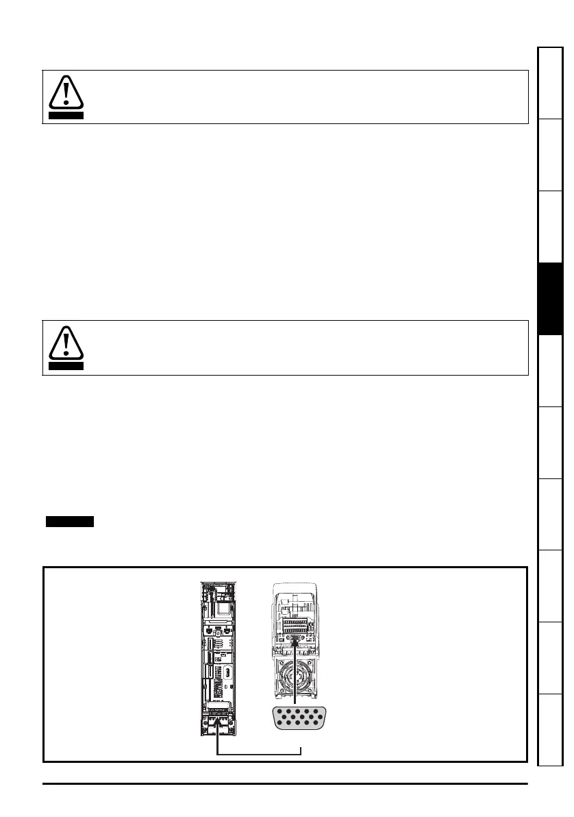
Figure 4-7 Location of position feedback connection
Electrochemical corrosion of grounding terminals
Ensure that grounding terminals are protected against corrosion i.e. as could be caused
by condensation.
The ground loop impedance must conform to the requirements of local safety regulations.
The drive must be grounded by a connection capable of carrying the prospective fault
current until the protective device (fuse, etc.) disconnects the AC supply.
The ground connections must be inspected and tested at appropriate intervals.
Refer to the Drive User Guide for information regarding the supported feedback devices
on the P1 and P2 position interface and the encoder stimulation output.
5
10
15
1
6
11
Drive encoder connector
Female 15-way D-type
Front view
End view
Unidrive M702 Getting Started Guide English iss3.book Page 35 Friday, August 29, 2014 2:33 PM

 Loading...


