6
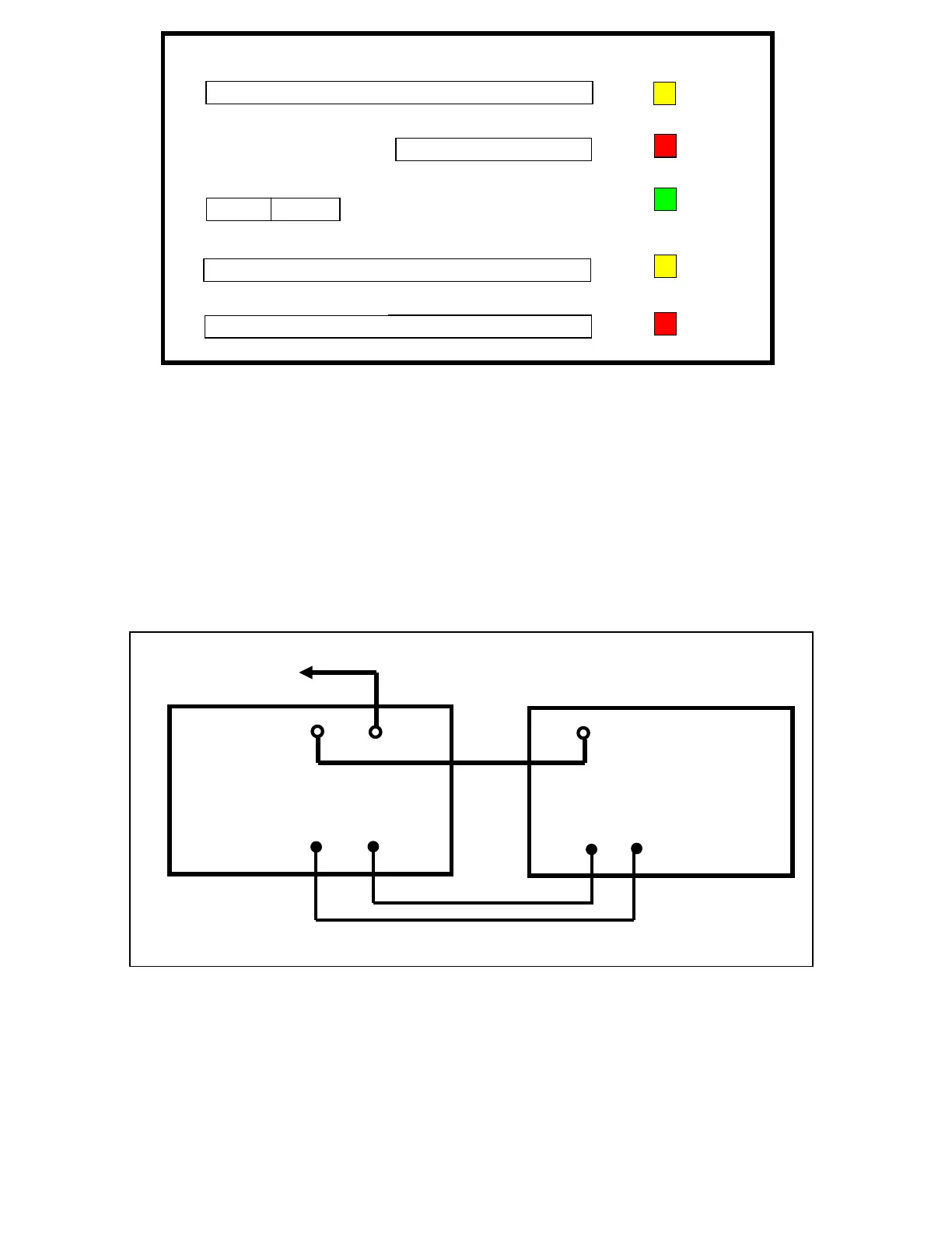
Figure 1. DX-2 Front Panel Display
7 ELECTRICAL CONNECTIONS
7.1 Connections to Transceiver / Exciter
Signal connections
Before making any connections, ensure that DX-2 is not connected to AC power, and the transceiver is not transmitting. Connect the
antenna first to the DX-2 output. Then connect the transceiver output to the DX-2 RF input. Plug the PTT lead into the RCA socket
marked PTT on the rear panel. If required, connect the ALC.
The most appropriate interconnection layout is shown in Figure 1 below. In this set-up, the transmit/receive relays in the DX-2 are
controlled directly by the transceiver or exciter.
Figure 2. Connections between DX-2 and station transceiver
7.2 Earth and mains connections
Power connections
Before connecting any power to the amplifier, make a good Earth connection to the screw with wing nut at the rear of DX-2. Make sure
the POWER switch on the front panel is in the OFF position. Then plug the power cable into the power point.
RF OUTPUT POWER
kW
REFLECTED POWER
W
PLATE VOLTAGE
kV
PLATE CURRENT
A
I
2
OVE
DRIVE
ON AIR
READY
SWR
FAULT
EMTRON
DX-2
STATION
TRANSCEIVER
RF IN
RF
OUT
TO
ANTENNA
ALC
ALC
PTT
Relay
In
ut
PTT
Relay
Out
ut