7
7.3 Terminating the power cable (export version)
As different countries have different standards for their power connections, all DX-2 amplifiers exported from Australia are supplied
with un-terminated power cables.
The green/yellow wire is connected to the amplifier chassis and MUST be connected to the safety ground of the AC mains supply. It
must NEVER be connected to one of the AC 'hot' wires. The brown and blue wires connect to the mains transformer input. The brown
wire is the "active", or "live". The blue wire is the mains neutral. Both wires are fused.
7.4 Operation at 230V, 220V and 200V (export version)
The Emtron DX-2 will normally arrive pre-set for the power source of the country the amplifier has been sold to. However if operation
to another mains voltage is required, the appropriate connection changes will be needed.
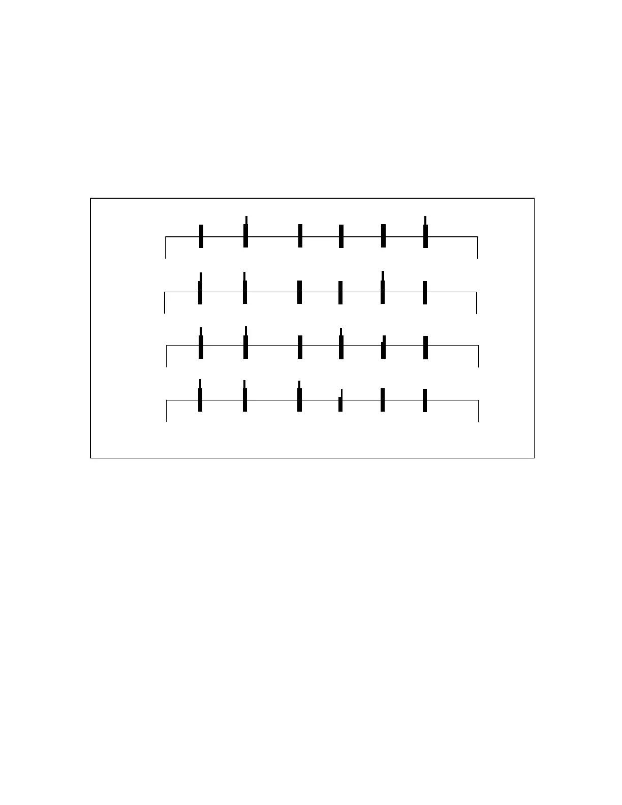
Figure 2 shows the transformer connections for 200V, 220V, 230V and 240V operation. If a change is required, this should be done
only by a qualified technician, after taking all the necessary safety precautions. See CAUTION on page 1.
PLEASE NOTE: The DX-2 should not be connected to a mains supply of less than 200V AC !
Figure 3. DX-2 Transformer AC Input Connections
8 DX-2 DESCRIPTION
8.1 RF Section
The RF section occupies the right hand side of the DX-2 (looking from the top - front). See picture in 1.1.
RF Switch and tuned circuits
At the front of the amplifier are two variable capacitors, for plate and load tuning and a band switch. Next to the switch is the “Pi” coil.
The “L” coil is wound on a ferrite torroid.
RF Sub-chassis
The GU84B tube is positioned on a separate RF sub-chassis. All the connections to the tube, except for the plate, are under this sub-
chassis. A 9-way heavy duty connector is used for inter-connections. The fan blows air into this sub-chassis, which is forced out
through the ventilation fins of the tube. The air temperature is sensed by two sensors placed above the tube. The sensors must stay in a
position close to horizontal. Make sure you are not pushing them down, too close to the tube, as high voltage exists between them. The
plate is connected to the RF network and to the choke supplying the 2500VDC voltage to the plate of the GU84B tube.
0
0
0
0
240
230
220
200
FAN
FAN
FAN
FAN
240 volt:
230 volt:
220 volt:
200 volt: