22
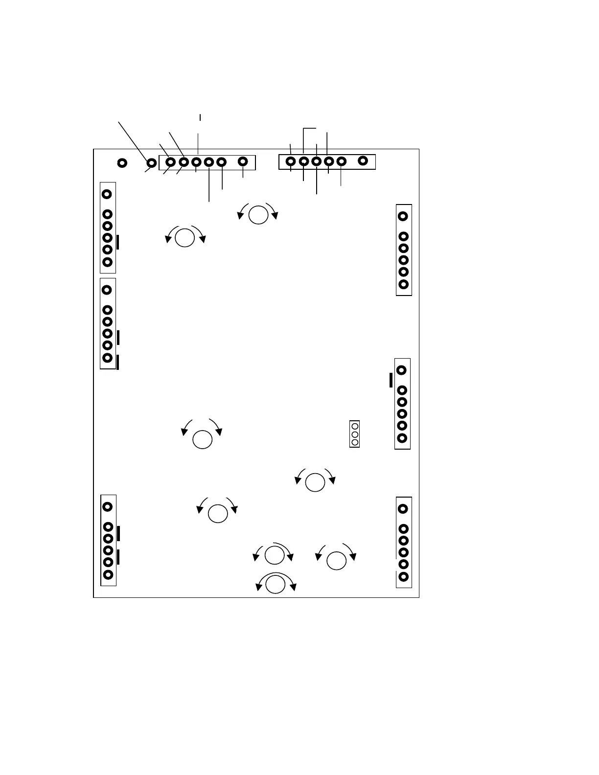
16.2 Control Board Connections and Adjustment Points
The drawing below shows all the connections to the control board and the adjustment points.
Unless you know very well what you are doing and you have a reason to do it, do not modify any adjustment!
LEGEND: WIRE COLOURS
X – Spare or no connection
Y/BLK – Yellow / Black
GRY/BLK – Grey / Black
PNK/BLK – Pink / Black
RED/BLK – Red / Black
Y/RED – Yellow / Red
GRY/BLU – Grey / Blue
RED/GRN – Red / Green
Y/GRN – Yellow / Green
WHT/BLK – White / Black
ORN/BLK – Orange / Black
GRN/RED – Green / Red
WHT/RED – White / Red
CONTROL BOARD - Bottom View
OD/TX
TXON
SWR
FAULT
SWR/FLT
PTT2
DISP
IG2F
IG2R
E
2
GND
O/DRV
BIAS
READY
RFIN
HLSW2
HLSW1
Y/GRN
W/R
GRY
PNK/BLK
W/BLK
X
RED
X
GRY/BLU
ORN/BLK
BLUE
X
T110-1
T110-2
GND
GND
300VAC2
300VAC1
100VAC1
100VAC2
10VAC1
10VAC1
10VAC2
10VAC2
LC1
SWR2
SWR1
SWR4
SWR3
LC2
VIOLET
WHITE
RED/GRN
BROWN
GRN/BRN
GRN/BRN
PNK/BLK
Y/BLK
Y/BLK
Y/RED
Y/RED
GREEN
YELLOW
YELLOW
GREEN
X
GRY/BLU
GRY/BLU
YELLOW
YELLOW
PINK
PINK
PINK
PINK
Y/GRN
12VP
RLY2
RLY1
STBY1
STBY2
QSK1
BLUE
ORN/BLKORNORN
Ip
GRY/BLK
PTT2
PTT1
IPTRIP
QSK2
22Vac
Y/GRN
QSK ONLY
RED
RED
W
VI
TP2
EBS
Off
Ig2Lim
SCREEN
BIAS
Pre-BIAS
EBS
SWR
IpTRIP
IPDispl
Sensitivity
-
+
+
+
+
+
-
-
+
-
+
-
-
-
+
On
-
Ip
Ip
Eg2
Ig
Sensitivity
Ip
V
(Solder side)