14
15 SERVICE
15.1 General
All Emtron amplifiers are built in a modular for. Most modules are common for the entire DX-n range.
This makes it easier to service the amplifier. However, this should only be attempted by suitable qualified people, with proper tools and
test equipment. Apart from the damaged that could be caused to the amplifier by unqualified intervention, the high voltages and
high RF power present in these amplifiers makes them extremely dangerous. Extreme care is recommended event to those very
experienced in this area.
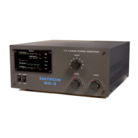
The following pages describe the main adjustments required on the DX-2 linear amplifier.
15.1.1 CONTROL BOARD
This procedure refers to adjustments made to the board already installed in the amplifier.
This would be required, for example, after replacing the tube or after certain repairs.
After a tube replacement only one or two adjustments are required: BIAS and (if EBS used): PRE-BIAS
15.1.1.1 PRE-BIAS ADJUSTMENT (Adjustment: POT7, marked PRE_BIAS)
The pre-bias is required when the Electronic Bias Switching (EBS) is used. If the EBS link is kept in OFF position, the pre-
bias does not need to be adjusted. PRE-BIAS must be adjusted before BIAS.
When EBS is activated (the default situation), keying the amplifier causes the plate current to stay cut off (as if the PTT
was off), until a small amount of drive is applied. The “Pre-bias” establishes a small plate current as soon as PTT is on.
The transition to full on is then less abrupt, while the tube dissipation is still reduced by using EBS.
PTT Off: Ip = 0
PTT On (no drive) and EBS on: Ip = Ipb (pre-bias current)
PTT On (no drive) and EBS off: Ip = Ip0 (standing current)
PROCEDURE:
Remove the cover and connect a voltmeter (+) to the test point TP2 (top corner). (-) to the chassis.
Make sure the EBS link is in the lower position (EBS ON).
With the amplifier running, wait the warm-up time. When READY, put OPR switch on and key the amplifier with NO
INPUT DRIVE. Read the voltage at TP2. Adjust POT7 (PRE-BIAS) to obtain the desired pre-bias current.
Recommended pre-bias currents (POT 7, PRE_BIAS):
DX1b: 10 to 30 mA 10 to 30 mV on the voltmeter Clockwise to reduce current
DX2 and
DX2SP:
15 to 40 mA 15 to 40 mV on the voltmeter Clockwise to reduce current
DX3: 20 to 60 mA 10 to 30 mV on the voltmeter Clockwise to increase
current
NOTE: the pre-bias current is not critical.
15.1.1.2 BIAS ADJUSTMENT (Adjustment: POT3, marked BIAS)
Adjust Pre-Bias before adjusting Bias.
This adjusts the plate standing current, with the EBS Off and the amplifier keyed with NO INPUT DRIVE.
PROCEDURE:
Remove the cover and connect a voltmeter to the test point TP2 (top corner).
Put the EBS link is in the upper position (EBS Off).
With the amplifier running, wait the warm-up time. When READY, put OPR switch on and key the amplifier with NO INPUT
DRIVE. Read the voltage at TP2. Adjust POT3 (BIAS) to obtain the desired bias current.
CAUTION: With a new tube, start at a low plate current. Rotate POT3 for minimum current before keying the amplifier.
With the adjustment in the wrong position, the plate current could reach very high values.
During this adjustment there is no output power. All the power taken from the high voltage supply is dissipated by the tube.
Be brief and quick. Put PTT on for a few seconds, then on. Repeat several times until the desired standing current is
achieved.