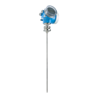
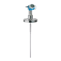
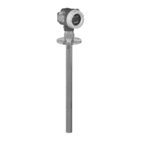
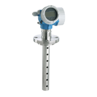
Levelflex FMP55
Endress+Hauser 83
3-point linearity protocol
The following notes must be taken into account if option F3 ("3 point linearity protocol") has
been selected in feature 550 ("Calibration").
Depending on the probe the 3 points of the linearity protocol are defined as follows:
A0021843
A Distance from reference point R to first measuring point
B Measuring range
C Distance from end of probe to third measuring point
LN Length of probe
R Reference point of the measurement
1 First measuring point
2 Second measuring point (centrally between first and third measuring point)
3 Third measuring point
Rod or coax probe
1)
LN ≤ 6 m (20 ft)
Divisible rod probe
LN > 6 m (20 ft)
Rope probe
LN ≤ 6 m (20 ft)
Rope probe
LN > 6 m (20 ft)
Position of 1st measuring
point
• FMP51/FMP52/FMP54 withoput gas phase compensation/
FMP55:
A = 350 mm (13.8 in)
• FMP54 with gas phase compensation, L
ref
= 300 mm (11 in):
A = 600 mm (23.6 in)
• FMP54 with gas phase compensation, L
ref
= 550 mm (21 in):
A = 850 mm (33.5 in)
A = 350 mm (13.8 in) A = 350 mm (13.8 in)
Position of 2nd measuring
point
centrally between 1st and
3rd measuring point
centrally between 1st and 3rd
measuring point
centrally between 1st and
3rd measuring point
centrally between 1st and
3rd measuring point
Position of 3rd measuring
point
measured from the
bottom end of the probe:
C = 250 mm (9.84 in)
measured from the top end of the
probe:
A+B = 5 750 mm (226 in)
measured from the
bottom end of the probe:
C = 500 mm (19.7 in)
measured from the top
end of the probe:
A+B = 5 500 mm (217 in)
Minimum measuring
range
B ≥ 400 mm (15.7 in) B ≥ 400 mm (15.7 in) B ≥ 400 mm (15.7 in) B ≥ 400 mm (15.7 in)
Minimum length of probe LN ≥ 1 000 mm (39.4 in) LN ≥ 1 000 mm (39.4 in) LN ≥ 1 250 mm (49.2 in) LN ≥ 1 250 mm (49.2 in)
1) also valid for divisible rods
The position of the measuring points may vary by ±1 cm (±0.04 in).
• For rod and rope probes the linearity check is performed with the complete device.
• For coax probes the electronics is mounted to a reference rod probe and the linearity check is
performed to this configuration.
• The linearity is checked under reference conditions.
 Loading...

