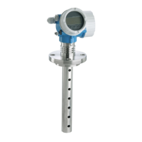
Levelflex M FMP40 FOUNDATION Fieldbus Mounting
Endress+Hauser 13
The following diagrams show typical loads for frequently occuring bulk solids as reference
values. The calculation is performed for the following conditions:
• Suspended probe (probe end not fixed at the bottom)
• Free-flowing bulk solid, i.e. mass flow. A calculation for core flow is not possible. In the event
of collapsing cornices, considerably higher loads can occur.
• The specification for tensile forces containes the safety factor 2, which compensates for the
normal fluctuation range in pourable bulk solids.
L00-FMP40xxx-05-00-00-en-007 L00-FMP40xxx-05-00-00-en-008
L00-FMP40xxx-05-00-00-en-006 L00-FMP40xxx-05-00-00-en-005
05
10 15 20 25 30 35
0
10
20
30
40
50
60
tensile force, 6 mm rope [kN]
level [m]
silica sand
smooth metallic walls
silo diameter 12 m
silo diameter 9 m
silo diameter 6 m
silo diameter 3 m
0
5
10
15
20
25
30
35
40
tensile force, 4 mm rope [kN]
05
10 15 20 25 30 35
0
2
4
6
8
10
12
14
16
18
tensile force, 6 mm rope [kN]
level [m]
polyethylene pellets
smooth metallic walls
silo diameter 12 m
silo diameter 9 m
silo diameter 6 m
silo diameter 3 m
0
1
2
3
4
5
6
7
8
9
10
11
12
tensile force, 4 mm rope [kN]
05
10 15 20 25 30 35
0
5
10
15
20
25
30
35
tensile force, 6 mm rope [kN]
level [m]
wheat
smooth metallic walls
silo diameter 12 m
silo diameter 9 m
silo diameter 6 m
silo diameter 3 m
0
2
4
6
8
10
12
14
16
18
20
22
24
tensile force, 4 mm rope [kN]
05
10 15 20 25 30 35
0
10
20
30
40
50
60
tensile force, 6 mm rope [kN]
level [m]
cement
smooth metallic walls
silo diameter 12 m
silo diameter 9 m
silo diameter 6 m
silo diameter 3 m
0
5
10
15
20
25
30
35
40
tensile force, 4 mm rope [kN]

 Loading...