Installation Micropilot FMR10
12 Endress+Hauser
5 Installation
5.1 Installation conditions
5.1.1 Installation types
A0030605
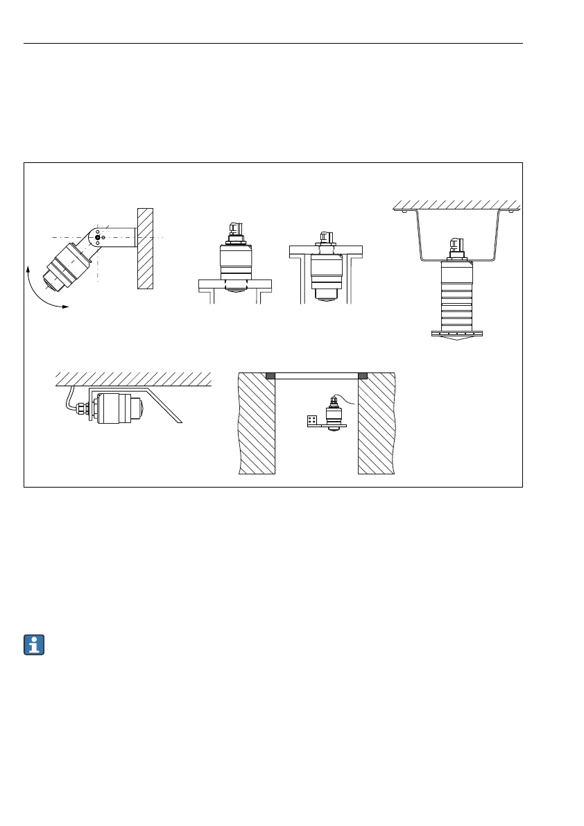
3 Wall, ceiling or nozzle installation
A Wall or ceiling mount, adjustable
B Mounted at front thread
C Mounted at rear thread
D Ceiling installation with counter nut (included in delivery)
E Horizontal installation in confined spaces (sewer shaft)
F Shaft wall mounting
Caution!
• The sensor cables are not designed as supporting cables. Do not use them for
suspension purposes.
• Always operate the device in a vertical position in free-space applications.
5.1.2 Nozzle mounting
The antenna should project out of the nozzle for optimum measurement. The interior of the
nozzle must be smooth and may not contain any edges or welded joints. The edge of the
nozzle should be rounded if possible.

 Loading...


