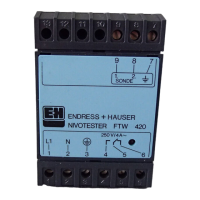
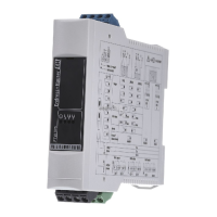
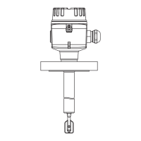
Calibration of the Nivotester FTC 421
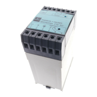
Controls Fig 11shows the calibration controls for the Nivotester FTC 421:
• Hook switch 1 matches the Nivotester to the capacitance of the
vessel. The settings are summarized in Table 3, Page 31.
• The top adjuster is used to set the switching point.
• Hook switch 2 sets the type of delay. Table 4 summarizes the
settings.
• Adjuster 2 sets the delay time.
• The green LED indicates that the unit is operational.
• The red LED indicates that the relay is energised (off) or
de-energised (lit).
* The relay switches immediately (0.5 s) if the level moves in the
opposite direction.
Green LED
Operational status
Hook switch 1 for
capacitance range
Hook switch 2 for
switching delay
Red LED
Relay status
Adjuster 1:
Switch point
Adjuster 2:
Switching delay
Fig. 11
Calibration controls of
Nivotester FTC 421
Switch setting Position Switching delay mode
1 Delay when probe uncovered*
2 Delay when probe covered*
Table 4
Effect of hook switch 2 setting on
switching delay mode
Nivotester FTC 420/421 Calibration
34
 Loading...
