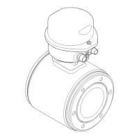
Proline Promag 50 Installation
Endress+Hauser
31
2.7.2 Turning the onsite display
2.7.3 Installing the wall-mount housing
"
Caution!
• Make sure that the ambient temperature does not exceed the permitted range.
•
lways install the wall-mount housing in such a way that the cable entries point downwards.
Mounted directly on the wall
A0007541
a. Press in the side latches on the display module and
remove the module from the cover plate of the
electronics compartment.
b. Turn the display to the desired position (max.
4 × 45° in both directions) and reset it onto the
cover plate of the electronics compartment.
A0007542
1. Connection compartment
2. Securing screws M6 (max. ø 6.5 mm (0.25");
screw head max. ø 10.5 mm (0.4")
3. Housing bores for securing screws
1
2
3
3
90 (3.54)
35 (1.38)
192 (7.56)
81.5 (3.2)
mm (inch)
Vendor Manual - Electromagnetic Flowmeter - Endress and Hauser - Model Proline Promag 50 - Operating Instructions

 Loading...


