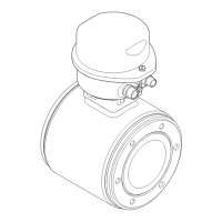
Wiring Proline Promag 50
36 Endress+Hauser
3.2 Connecting the remote version connecting cable
3.2.1 Connecting cable for Promag W, P and L
Connecting cable termination
Terminate the signal and coil current cables as shown in the figure below (Detail A).
Fit the fine-wire cores with cable end ferrules (Detail B).
Signal cable termination
Make sure that the cable end ferrules do not touch the wire shields on the sensor side! Minimum
distance = 1 mm (0.04 in), exception "GND" = green cable.
Coil current cable termination
Insulate one core of the three-core cable at the level of the core reinforcement; you only require
two cores for the connection.
Sensor Transmitter
mm (inch)
a* = 170 (6.69)
b* = 20 (0.79)
c = 80 (3.15)
d = 17 (0.67)
e = 8 (0.31)
f = 50 (1.97)
g = ≥ 1 (≥ 0.04)
a0008171
mm (inch)
a* = 100 (3.94)
b = 80 (3.15)
c = 50 (1.97)
d = 17 (0.67)
e = 8 (0.31)
m
= Cable end ferrules, red, ∅ 1.0 mm (0.04");
n
= Cable end ferrules, white, ∅ 0.5 mm (0.02")
* = Stripping for armored cables only
Sensor Transmitter
mm (inch)
a* = 160 (6.3)
b* = 20 (0.79)
c = 70 (2.76)
d = 50 (1.97)
e = 8 (0.31)
f = 10 (0.39)
a0008172
mm (inch)
a* = 90 (3.54)
b = 70 (2.76)
c = 50 (1.97)
d = 10 (0.39)
e = 8 (0.31)
m
= Cable end ferrules, red, ∅ 1.0 mm (0.04");
n
= Cable end ferrules, white, ∅ 0.5 mm (0.02")
* = Stripping for armored cables only
A
B
GND
m
m
m
m
n
n
n
n
a*
b
c
d
e
m
n
m
n
n
a*
c
f
e
b*
d
g
GND
Vendor Manual - Electromagnetic Flowmeter - Endress and Hauser - Model Proline Promag 50 - Operating Instructions

 Loading...


