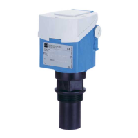
Prosonic T FMU30
Endress+Hauser 11
Installation conditions for flow
measurements
• Install the instrument at the inflow side (B), as close above the maximum water level H
max
as possible (take
into account the blocking distance BD).
• Position the instrument in the middle of the channel or weir.
• Align the sensor membrane parallel to the water surface.
• Keep to the installation distance of the channel or weir.
Example: Khafagi-Venturi flume
A0019607
A Khafagi-Venturi flume BD Blocking distance
B Inflow E Empty calibration
C Outflow F Full calibration
V Direction of flow
Example: Triangular weir
L00-FMU30xxx-17-00-00-xx-012
BD Blocking distance
E Empty calibration
F Full calibration
(= F)
min. 3 H
H
min. 2 H
a
min. 2 H
BD
E
max.
max.
max.
max.
Заказывайте на сайте: www.tinnova.ru/endress_hauser/ || Эл. почта: info@tinnova.ru

 Loading...


